
Summary/Overview:
Over the last few years, we have seen more beginner and moderate reefers becoming more and more inclined to attempt DIY projects. Anything from building a custom roller mat or an algae turf scrubber to attempting a stand build using two-by wood. With LED’s becoming more popular, the need for changing diodes for spectrum preference changes as well as burnt out diodes is becoming more of a norm.
This article will focus on the replacement of LED diodes and cover the following:
This article will not cover specific LED models, recommended spectrum, the LED vs debates, or other lighting specific questions. There are many fine articles and threads available that discuss these and other great topics. This article will also not cover and is not intended to cover all safety aspects of the project. Please consult with a local expert, if you feel it is required.
So let’s get started!
Tools Needed:
You do not need anything fancy here. I am using a basic soldering iron made by Weller.
Supplies Needed:
How To:
First, I’ll take you through opening your fixture. Please note, you will likely void any warranty by doing so. This can be confirmed by contacting the unit’s manufacturer.
Before starting, I recommend fully reading over the steps as well as the Tips and Tricks outlined below prior to starting the project. I also recommend that you program your unit prior to starting and if it does not have a battery backup, I recommend at least being familiar with how to program your unit. This will significantly help if you need to troubleshoot at the end!
Step 1: Unplug the unit. I cannot stress this enough! Never open any type of equipment while the unit is connected to a power source, even if the unit is powered off. The unit must be unplugged! This is not only dangerous for you, but for the equipment also.
Step 2: There can be multiple screws on the outside of a fixture. It is best to start with the screws that are around the perimeter of the unit. In the case of the fixture I am using to show you, there were a total of ten screws (See the red dots on the images for those visible). Four on the top side of the unit and three each along the front and back side of the fixture.
Step 3: Next, test the fixture cover by lightly pulling the cover off of the unit. If this is difficult, there is likely a screw that was missed in the above steps.
Once you get the top open enough to peek inside of the unit, there might be an electrical connection or two that will need to be disconnected to be able to fully remote the top. Disconnect these after reading the below comments!
Step 4: Now that you have removed these electrical connections and have gained access to the unit, open it and lay it flat.
TIP/Trick: This is a great opportunity to take a picture for reference later, if needed.


At this point, you can note if any additional parts need to be removed to gain access to the lenses. In other lights I have worked on in the past, you had full access to the lenses at this time and others you had a similar design as shown above. In today’s case, I had an additional six screws to remove (around the heat sinks and plate) to gain access to each side.
Step 5: Once these were removed, I was able to carefully flip over the plate and heatsink and expose the lenses. The lenses shown are very common in our reefing application and pop off very easily. A light pry and twist may be required.

Step 6: Removing the existing LED Diode. I have found the easiest way to accomplish this is while lightly gripping the original diode with a pair of needle nose pliers, user the soldering iron to head the solder on one side of the unit. As the solder becomes molten, lift up with the pliers on that side of the diode. Once the one side is free, move to the next side and perform the same step.
TIP/Trick:

Step 7: Installing the new diode! Please read the Tips/Tricks prior to moving ahead as these are key to the installation.
TIP/Tricks:

Also, setting your personal expectation here is key… You are not a machine and likely you will not make the solder connection look as good as the manufacturer did, and you don’t need to!
Step 8: If you would consider yourself entry-level to this type of DIY project or want to be extra careful, go back up and read the Final Tip to Step 7! Really!
Continuing on. Repeat Step 6-7 until you have replaced all of the diodes you wish to replace.
These simply snap on over the diode. A slight and easy twisting motion can be used to ensure they are on all the way.
Step 9: Re-install any screws you may have Step 5. You may also want to revisit Step 4 for the picture you might have taken if you are unsure!
Step 10: Ensure you have no additional screws or lenses… If you do, open that puppy back up and figure out where they go! If not, let’s get this light plugged in *once it is fully assembled* and turn on the unit to validate our work.
Left side shows new LEDs while the right shows the manufacturers configuration. (I removed the red and green diodes in favor of a warm white.)

If you have any concerns at this point, proceed to the troubleshooting section below. If not, congratulations!
Troubleshooting:
Below is a list of items to check after installing a new LED and the fixture or channel is not lighting up.
Over the last few years, we have seen more beginner and moderate reefers becoming more and more inclined to attempt DIY projects. Anything from building a custom roller mat or an algae turf scrubber to attempting a stand build using two-by wood. With LED’s becoming more popular, the need for changing diodes for spectrum preference changes as well as burnt out diodes is becoming more of a norm.
This article will focus on the replacement of LED diodes and cover the following:
- Tools needed
- Supplies required
- Instructional How-to
- Tips and Tricks
- Some troubleshooting, if required.
This article will not cover specific LED models, recommended spectrum, the LED vs debates, or other lighting specific questions. There are many fine articles and threads available that discuss these and other great topics. This article will also not cover and is not intended to cover all safety aspects of the project. Please consult with a local expert, if you feel it is required.
So let’s get started!
Tools Needed:
You do not need anything fancy here. I am using a basic soldering iron made by Weller.
- Screwdriver Set
- Needle Nose Pliers
- Solder Iron
- A few small bowls or containers (keep the screws safe and organized)
Supplies Needed:
- Thermal Grease or Paste (stay away from epoxy/adhesive thermal compounds)
- Electrical Solder
- LEDs that match your application
- Wattage - typically 1w or 3w bulbs for our application
- Light wavelength output (measured in Nanometer or nm)
- Heat sink attached? (ex. Star or standalone diode)
- A diagram of your bulbs. This is needed if you are changing spectrum and looking to replace specific bulbs (most manufacturers supply this, otherwise you should draw this up prior to opening the unit). If you are replacing a dead bulb, note which one is dead before opening the unit!
How To:
First, I’ll take you through opening your fixture. Please note, you will likely void any warranty by doing so. This can be confirmed by contacting the unit’s manufacturer.
Before starting, I recommend fully reading over the steps as well as the Tips and Tricks outlined below prior to starting the project. I also recommend that you program your unit prior to starting and if it does not have a battery backup, I recommend at least being familiar with how to program your unit. This will significantly help if you need to troubleshoot at the end!
Step 1: Unplug the unit. I cannot stress this enough! Never open any type of equipment while the unit is connected to a power source, even if the unit is powered off. The unit must be unplugged! This is not only dangerous for you, but for the equipment also.
Step 2: There can be multiple screws on the outside of a fixture. It is best to start with the screws that are around the perimeter of the unit. In the case of the fixture I am using to show you, there were a total of ten screws (See the red dots on the images for those visible). Four on the top side of the unit and three each along the front and back side of the fixture.
Tip/Tricks:

- Once removed, put these screws in a container so they are not misplaced.
- Take note of any screws that are different in length or width and give each of these their own container.
Step 3: Next, test the fixture cover by lightly pulling the cover off of the unit. If this is difficult, there is likely a screw that was missed in the above steps.
Once you get the top open enough to peek inside of the unit, there might be an electrical connection or two that will need to be disconnected to be able to fully remote the top. Disconnect these after reading the below comments!
Tip/Tricks:

- If you are new to this type of DIY work or have a sub-par memory, I recommend a labeling system. Number or color code small pieces of masking tape at each connection removed.
- The same can be done to the bowls of screws. That way if there were any odd length screws, you know the correct location at the end of the project.
Step 4: Now that you have removed these electrical connections and have gained access to the unit, open it and lay it flat.
TIP/Trick: This is a great opportunity to take a picture for reference later, if needed.
At this point, you can note if any additional parts need to be removed to gain access to the lenses. In other lights I have worked on in the past, you had full access to the lenses at this time and others you had a similar design as shown above. In today’s case, I had an additional six screws to remove (around the heat sinks and plate) to gain access to each side.
Step 5: Once these were removed, I was able to carefully flip over the plate and heatsink and expose the lenses. The lenses shown are very common in our reefing application and pop off very easily. A light pry and twist may be required.
Step 6: Removing the existing LED Diode. I have found the easiest way to accomplish this is while lightly gripping the original diode with a pair of needle nose pliers, user the soldering iron to head the solder on one side of the unit. As the solder becomes molten, lift up with the pliers on that side of the diode. Once the one side is free, move to the next side and perform the same step.
TIP/Trick:
- Do not let the soldering iron sit the panel that the LED is affixed to. Your goal is only to melt the solder enough to remove the diode.
- Once the diode is removed, if it is working, place it in a container with the spectrum marked (in case you need or want it in the future).
- Some cheaper soldering irons cool down with a breeze or heavy breathing so if you are having trouble, that might be the cause!
Step 7: Installing the new diode! Please read the Tips/Tricks prior to moving ahead as these are key to the installation.
TIP/Tricks:
- Thermal grease / paste is not optional. You cannot rely on the existing paste on the unit.
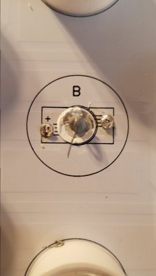
- The two sides of the diode are not the same. One side will have a small hole in the shape of a minus sign “-“ that indicates the diodes negative connection. Most boards will indicate the positive connection. If not, note which way the existing diode is installed.
- You do not want to use too much solder, but you want to ensure there is a solid connection. In fact, there are times when I don’t add any because the existing solder is enough to ensure a solid connection.
- If you are working with multiple bulb types, make sure you find the correct one to install!
Also, setting your personal expectation here is key… You are not a machine and likely you will not make the solder connection look as good as the manufacturer did, and you don’t need to!
7-A: Great! Moving Ahead. Grab the new diode and match up the positive and negative side of the diode to the board.
7-B: Add a small glob of thermal paste/grease to the board where the diode sits.
7-C: Select on side to start and re-heat the existing solder on the board. I tend to do this and use the soldering iron to push the metal connection of the diode into the molten solder. If there is not enough on the board, go ahead and top it with a small amount to ensure proper connection.
7-D: Repeat with the other side ensuring the diode is pushed down completely and the thermal paste/grease is compressed.
Final Tip/Trick for Step 7… for those new to this. This is a great time to reconnect and put the unit back together and determine if what you have done has worked. Doing it now, is much easier to troubleshoot a single diode replaced, versus two or five… If you have any issues, skip down to the troubleshooting section!


Step 8: If you would consider yourself entry-level to this type of DIY project or want to be extra careful, go back up and read the Final Tip to Step 7! Really!
Continuing on. Repeat Step 6-7 until you have replaced all of the diodes you wish to replace.
These simply snap on over the diode. A slight and easy twisting motion can be used to ensure they are on all the way.
Step 9: Re-install any screws you may have Step 5. You may also want to revisit Step 4 for the picture you might have taken if you are unsure!
Step 10: Ensure you have no additional screws or lenses… If you do, open that puppy back up and figure out where they go! If not, let’s get this light plugged in *once it is fully assembled* and turn on the unit to validate our work.
Left side shows new LEDs while the right shows the manufacturers configuration. (I removed the red and green diodes in favor of a warm white.)
If you have any concerns at this point, proceed to the troubleshooting section below. If not, congratulations!
Troubleshooting:
Below is a list of items to check after installing a new LED and the fixture or channel is not lighting up.
- The diode I replaced is not working including all LED’s on that channel..
- If you did not fully reassemble your unit, sometimes the manufacturers will ground to the case and therefore through the screws. You might have an open ground causing the channel to not light up. Mitigation – fully assemble the unit prior to testing.
- If you missed re-attaching the green wire (ground) to the unit, this may cause the lights to flicker on and off or not turn on at all. Mitigation – reopen the unit and look for any missed screws or connections.
- Did you reattach all electrical connections? Mitigation – reopen and inspect the unit and that there are no wires not connected. Refer to the picture in Step 4 (every once in a while, there are open connections on boards. These can be ignored).
- LED I just installed is not working.
- Validate the LED is installed correctly (remember, check the + and -)
- Sometimes, you just get a bad LED. Try replacing it.
- The LED I installed is burning out prematurely (this is more rare)
- Did you use new thermal paste/grease? If not, that could likely be the issue. Mitigation – replace the bulb and use a quality thermal grease.
- Did you ensure the LED was pressed onto the heat sink or panel? Whether or not thermal grease is present, if there is too much of a gap, the LED may have burned out due to lack of head dissipation. Mitigation – replace the bulb with new thermal grease and ensure the bulb is pressed tightly to the heat sink or panel.