Vivid Creative Aquatics

Upgrade Your Flow!
View Badges
Joined
Oct 12, 2017
Messages
1,375
Reaction score
1,936
Location
Phoenix, AZ
Rating - 0%
0   0   0
IMG_20210427_123545_027.jpg The VCA 134-Gallon Cube - Random Flow Generator Powered Mixed Reef!

The first of two new offices tanks are officially under way, and I can’t wait to share it here on Reef-2-Reef

Our goal with this tank is to build a mixed reef tank with a unique flow solution that utilizes just Random Flow Generator® Nozzles to flow the entire tank.

Here are the initial details:

The Display Tank – 134 Gallons
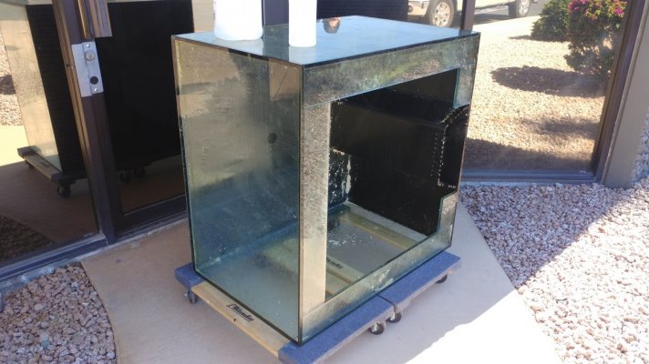
The Display Tank started out as a used Lemar 34x34x24 cube tank that we acquired from a local hobbyist - why build brand new when you can recycle – right?

The original configuration had the center overflow positioned on the back wall, with the standard three holes drilled in the bottom – two 1in holes for return lines and a single 1.5in hole for the drain.

The first task was to remove the back overflow box and prep the existing holes for the closed loop.
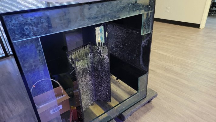
20210221_124650.jpg 20210324_110259.jpg

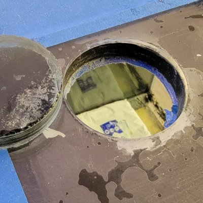
Next – we needed to drill 4 new holes – two for the returns and two for the EShopps Eclipse Overflow box. We did not have a way of running a continuous flow of water over the drill bit, without making a huge mess in the front lobby, so we use Glass Cutting Oil. Worked well. The process made some free sand. It if were not for the oil, I probably could have used it in a small nano tank.
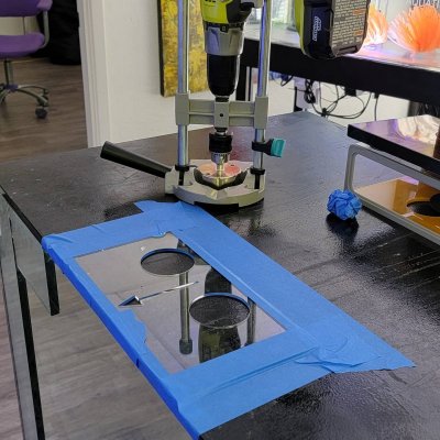
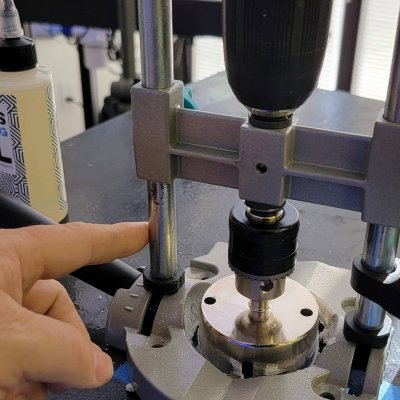
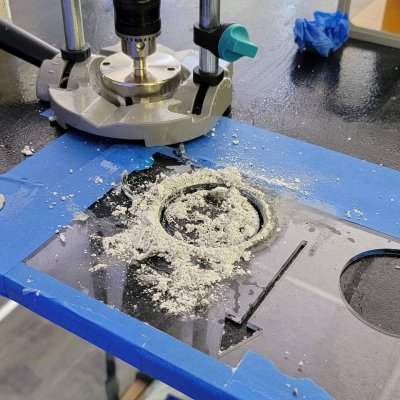
IMG_20210423_095813_781.jpg IMG_20210423_095813_805.jpg IMG_20210423_095813_830.jpg IMG_20210423_095813_845.jpg


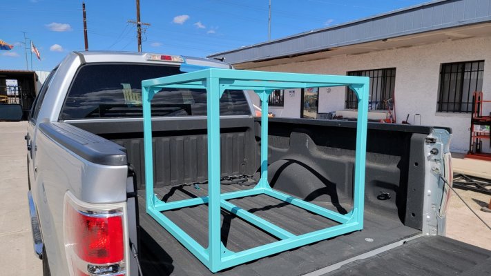
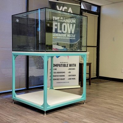
20210316_140223.jpg The Custom Steel Stand

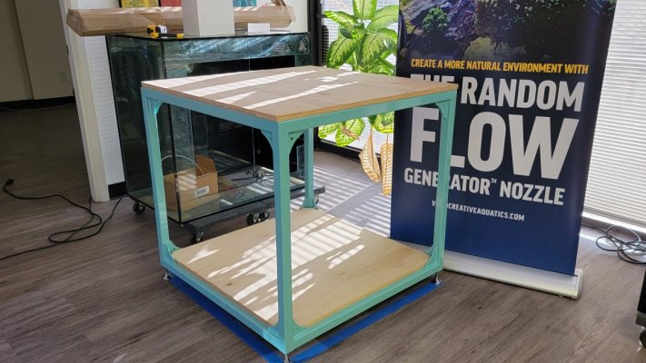
The stand is a custom steel stand constructed out of 1 1/2" tube steel with 3/8 inch wall thickness. It’s pretty heavy duty, while still maintaining a minimalist appearance. We had it powder coated with an Aqua Blue gloss finish.

20210317_170903.jpg 20210316_145514.jpg

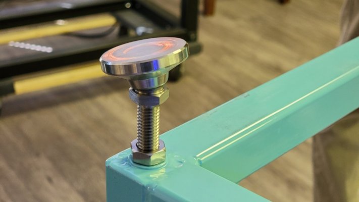
We added a 3/4in Burch plywood base and platform. The floor in tour office suite is severely uneven. You can see it, but it because very obvious when you try and level a tank. So I designed the stand to use heavy duty leveling feet.


The first Challenge - the size of the tank vs the size of the door
One of the first challenges with this tank was the physical size of the tank in relationship to the size of the front door to our office. The maximum door width is 32 inches wide. The tank came in on its side with no problem. However, the stand had a limitation of 32 inches as a max dimension. As a result, the stand is a little shorter than I would have liked.

The height of the steel stand is 32 inches. The adjustable feet add another 3 inches to the overall height. The final height of the stand is 35in. Add to that the 3/4in birch board used as the base under the tank and the top of the tanks sits just shy of 60in tall.
20210427_120104.jpg


The Dual Closed Loop - with Shared Drain

This build features a dual closed loop with shared drain. This will provide most of the flow in this tank and will be created using two of our 1in RFGS100LL Random Flow Generators®

This proved to be the second major challenge. The original design was to have the pumps mounted underneath the tank, upside down and out of the way. However, the sheer size of some of the plumbing fittings such as 1 1/2in elbows and Union Ball Valves made that nearly impossible.

The second challenge was being able to supply both pumps from a single drain. The drain is 1 1/2 inches which is more than enough for a single pump, but may be a bit restrictive for dual pumps. The biggest issue was friction caused by high velocity of flow through this pipe which could then lead to cavitation as the two pumps worked against one another for supply. To get around that and to minimize friction, we needed to reduce the velocity through the pipe.

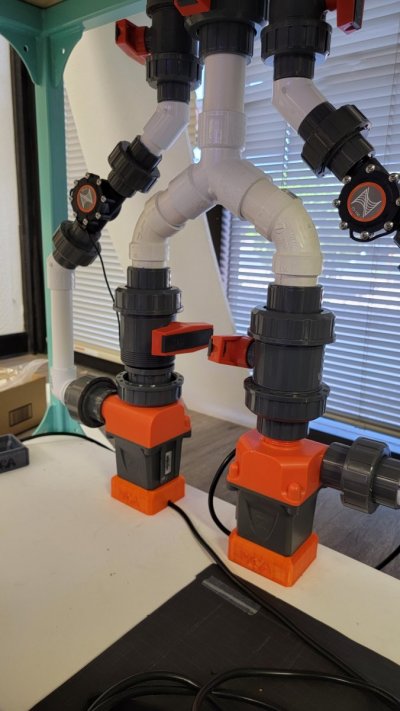
With the help of friend who knows more than I do about friction and flow, we came up with this design that uses a 60 degree 3-way Y to split the drain and create two separate runs leading to each pump. This effectively reduces the velocity in the sections leading to the pumps and minimizes the chances of starving either of the pumps.

20210705_174330.jpg


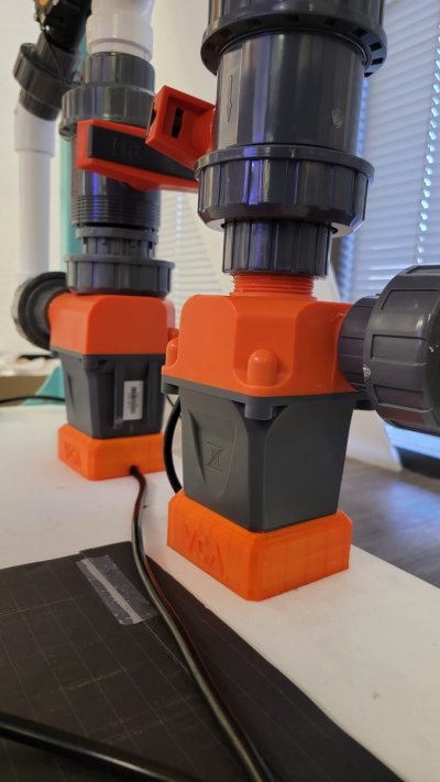
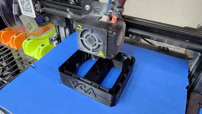
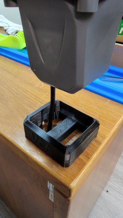
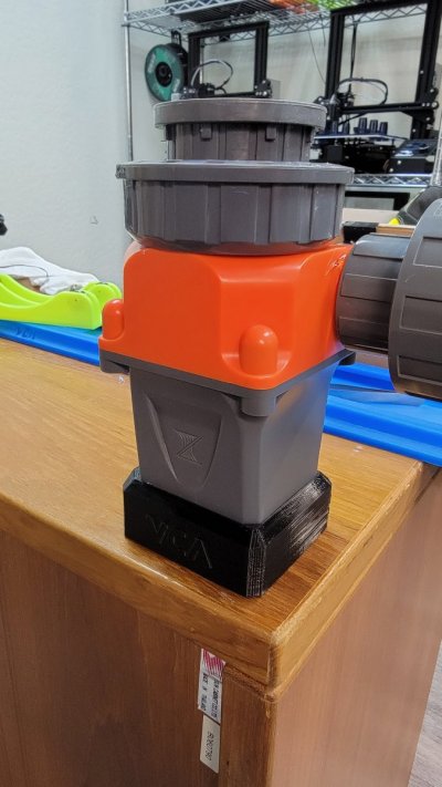
I mounted the pumps vertically to facilitate better flow into the inlet, but that presented a challenge. We didn't want to leave them dangling and unsupported. So, I designed and 3D printed these bases. The base helps to support the pumps and secure it in place. it also take stress off the plumbing. Once everything is done, I'll drill a hole underneath them and rout the wires underneath the platform so they are out of site.
20210705_130839.jpg

20210705_134824.jpg 20210705_134816.jpg 20210707_112122.jpg 20210707_112128.jpg


In our initial testing, the dual closed loop with shared drain design seems to work quite well. Both pumps can be run at 100% without any apparent issue. We’ll share some flow numbers once we get the Apex hooked up. Here are some videos of the iniitial flow testing.


The Flow Plan
The primary flow will be handled with this dual close loop. Each side of the loop is powered by its own Cor20 return pump. These will then be controlled through a Neptune Apex to vary the speed of each loop. The plan here is to slowly alternate the power between the two pumps at opposite intervals. So for instance over the 12 hour period the left pump will ramp from 80% down to 20%, while the right side will ramp up from 20% to 80%.

1626829967033.png


This will hopefully create a sort of switching dominate current inside the tank. At the peak while the left side is at 80% and the right side is at 20%, the dominant current will be going in a general clockwise direction around the tank. Mid-day will be 50% power on both loops, so just chaotic randomized motion. Then towards the end of the day, the general flow direction will switch to a counter-clockwise direction.

A Reverse Check Valve Design
Returns are going to be kind of interesting because we want to feature another unique setup here a swell. We needed a way to run a undersized sump, and still be able to drop the return lines well below the water line without fear of back siphon and an overflow. Every 1 inch of water level in the display tank is approx 5 gallons of water. So we drew inspiration from Marc Levinson of Melev's reef reverse check valve design.

Reverse check valve is interesting because it will break the siphon almost instantly when power is cut to the return pump. But you need to configure it correctly to work. Basicly the main lien that feed the two returns needed to be ABOVE the returns, and the valve needs to be either inline or above that. Here's what i have planned:

1626830131868.png


Basically, you place a check valve in reverse at the highest point within your plumbing. Pressure from the return pump presses on the check valve and closes it allowing water to then be routed to the return line.

When power to the pumps is cut, the pressure releases and allows the check valve to then open. Once the valve opens, it draws in air and breaks the siphon.

This will allow me to accomplish the two things i needed

First I'll be able to drop the return lines, which will also have RFG nozzles as far below the waterline as I like.

Second it would allow me to run a slightly undersized sump, giving me more room for other equipment underneath the tank. This is important because a cube set up is generally a little more difficult to deal with than your more common rectangular setup in terms of placing equipment.


Stay Tuned
So that's where we're at so far. The tank sits at about 3/4 of the way full of water as we test the closed loops. Comment below and let me know what you think . And stay tuned as we progress with this build. Next up is the sump design
 
Last edited:

revhtree

Owner Administrator
View Badges
Joined
May 8, 2006
Messages
47,718
Reaction score
86,678
Rating - 100%
1   0   0
Ok this thread is exciting! @Daniel@R2R check this out!
 
OP
OP
Vivid Creative Aquatics

Vivid Creative Aquatics

Upgrade Your Flow!
View Badges
Joined
Oct 12, 2017
Messages
1,375
Reaction score
1,936
Location
Phoenix, AZ
Rating - 0%
0   0   0
Looks nice.

I do not think your water level will drop as far as you have indicated with the reverse check valve.
I agree to some extent - I think that would be the worse case scenario.

The Reverse check valve design will give me some leeway in how deep i want to push the return lines. It will also give me more options for the sump. since the stand is kinda short, the height of the sump will need to be a little short as well. So less reserve space. At least that's my thinking here.
 

KStatefan

2500 Club Member
View Badges
Joined
Jun 24, 2015
Messages
4,110
Reaction score
3,988
Location
MHK
Rating - 0%
0   0   0
I agree to some extent - I think that would be the worse case scenario.

The Reverse check valve design will give me some leeway in how deep i want to push the return lines. It will also give me more options for the sump. since the stand is kinda short, the height of the sump will need to be a little short as well. So less reserve space. At least that's my thinking here.

I was just looking at the returns the bottom of the weir is your low point.
 
OP
OP
Vivid Creative Aquatics

Vivid Creative Aquatics

Upgrade Your Flow!
View Badges
Joined
Oct 12, 2017
Messages
1,375
Reaction score
1,936
Location
Phoenix, AZ
Rating - 0%
0   0   0
I might be missing something but I think it shouldn't go lower then this as long as that check valve lets air in.


I see what you're saying - You are correct.

I think that line i have labeled for where the water level would drain to WITH the Reverse Check Valve was in error - and left in place from a previous design I had done, (not shown here) where the horizontal run was in line with the return holes.

We determined that that with the pipe in lien with the return holes that it would drain to at least that level and could possible even drain further with the valve acting more like drain vent than an siphone break - So we raised it.
 
Last edited:

KStatefan

2500 Club Member
View Badges
Joined
Jun 24, 2015
Messages
4,110
Reaction score
3,988
Location
MHK
Rating - 0%
0   0   0
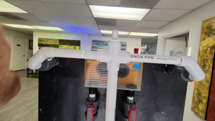
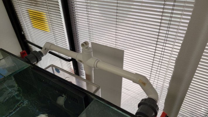
Here is the dry-fit of the return line plumbing that has the Reverse Check vlve setup. Nothing is glued yet, but I wanted to get an idea of hwo this woudl look lik in real lifve.


I see what you're saying - You are correct.

I think that line i have in my labeled for where the water level would drain to WITH the Reverse Check Valve, was in error - and left in place from a previous design I had done, (not shown here) where the horizontal run was in line with the return holes.

We determined that that with the pipe in lien with the return holes that it would drain to at least that level and could possible even drain further with the valve acting more like drain vent than an siphone break - So we raised it.

I edited my post above. I was just thinking about the water level from reverse siphon thru the returns and totally skipped the water level from the weir still draining.

I should have looked at my picture for a couple minutes prior to posting.
 
OP
OP
Vivid Creative Aquatics

Vivid Creative Aquatics

Upgrade Your Flow!
View Badges
Joined
Oct 12, 2017
Messages
1,375
Reaction score
1,936
Location
Phoenix, AZ
Rating - 0%
0   0   0
Here is the dry-fit of the return line plumbing that has the Reverse Check Valve setup. Nothing is glued yet, but I wanted to get an idea of how this would look like in real life.

Sorry for the wonky photos - the tank is somewhat close to the wall, and it's hard to get nice straight shots.


20210716_112604.jpg


I'm considering painting the upper part of the plumbing a flat black once it's all done to help make it less obviosue form the front. Standing a few feet form the tank, it;s hard to see the plumbing sticking up, but you can see the check vavle.

20210716_112558.jpg


20210713_175534.jpg 20210713_175420.jpg
20210716_112621.jpg
 

kenbennedy

Active Member
View Badges
Joined
Jun 5, 2021
Messages
172
Reaction score
197
Location
Houston
Rating - 0%
0   0   0
Here is the dry-fit of the return line plumbing that has the Reverse Check Valve setup. Nothing is glued yet, but I wanted to get an idea of how this would look like in real life.

Sorry for the wonky photos - the tank is somewhat close to the wall, and it's hard to get nice straight shots.


20210716_112604.jpg


I'm considering painting the upper part of the plumbing a flat black once it's all done to help make it less obviosue form the front. Standing a few feet form the tank, it;s hard to see the plumbing sticking up, but you can see the check vavle.

20210716_112558.jpg


20210713_175534.jpg 20210713_175420.jpg
20210716_112621.jpg
Good writeup, it is great to see someone setting up the reverse check valve. I want to use this approach in my next tank.
 
OP
OP
Vivid Creative Aquatics

Vivid Creative Aquatics

Upgrade Your Flow!
View Badges
Joined
Oct 12, 2017
Messages
1,375
Reaction score
1,936
Location
Phoenix, AZ
Rating - 0%
0   0   0
Good writeup, it is great to see someone setting up the reverse check valve. I want to use this approach in my next tank.
I've always been curious about it as well - and finally had an opportunity to do one.

Cant wait to actually test it out. I think the biggest challenge will be maintenance on the valve, and making sure algae doesn't grown inside and cause it to fail.

I plan on designing and and 3D printing a snap-on cover for the valve, to help block light from getting in.

1626885929165.png
 

kenbennedy

Active Member
View Badges
Joined
Jun 5, 2021
Messages
172
Reaction score
197
Location
Houston
Rating - 0%
0   0   0
I've always been curious about it as well - and finally had an opportunity to do one.

Cant wait to actually test it out. I think the biggest challenge will be maintenance on the valve, and making sure algae doesn't grown inside and cause it to fail.

I plan on designing and and 3D printing a snap-on cover for the valve, to help block light from getting in.

1626885929165.png
Great idea. I would not have thought of that.
 
OP
OP
Vivid Creative Aquatics

Vivid Creative Aquatics

Upgrade Your Flow!
View Badges
Joined
Oct 12, 2017
Messages
1,375
Reaction score
1,936
Location
Phoenix, AZ
Rating - 0%
0   0   0
Of course you 3D printed a base for the pump :p
yes.. yes i did ;Joyful

The goal here was to hide as much of the wiring as possible since the sump area will remain open. The stands will help me with that by allowing me route the wiring underneath stand.

Once everything is finalize, I'll also be securing the stands to the sump area base using a wood screw to help take any excess strain off the plumbing and bulkheads under the tank. I may even use some of the left over close cell foam (wet suite material) i have left over form under the tank to go under the stands to help minimize any vibration/noise.
1626889116913.png


Here how this stand works


shadow1013

Well-Known Member
View Badges
Joined
May 8, 2015
Messages
847
Reaction score
340
Location
Orlando, FL
Rating - 0%
0   0   0
Wonder if you could do a small base in TPU to help with vibrations. What did you make the base out of, PLA or PETG? Is that the same material you use for the nozzles as well?
 
OP
OP
Vivid Creative Aquatics

Vivid Creative Aquatics

Upgrade Your Flow!
View Badges
Joined
Oct 12, 2017
Messages
1,375
Reaction score
1,936
Location
Phoenix, AZ
Rating - 0%
0   0   0
Wonder if you could do a small base in TPU to help with vibrations. What did you make the base out of, PLA or PETG? Is that the same material you use for the nozzles as well?
That's not a bad idea. I could get something with a good shore hardness of at least 75 to 85

These where printed in PETG - mostly because that's what we have a lot of around here, since the RFG is manufactured with PETG. And, I had an Orange in stock that matched up with the pump.

I wonder if this is a good opportunity to use the IDEX (dual extrusion) printers to try some mixed-materials prints.
 

shadow1013

Well-Known Member
View Badges
Joined
May 8, 2015
Messages
847
Reaction score
340
Location
Orlando, FL
Rating - 0%
0   0   0
I haven't done mixed material, but I do print in either TPU or PLA. Don't really have the space to do PETG with the fumes. Do you know if PLA is reef safe? Want to make sure before I try and print some accessories.
 
OP
OP
Vivid Creative Aquatics

Vivid Creative Aquatics

Upgrade Your Flow!
View Badges
Joined
Oct 12, 2017
Messages
1,375
Reaction score
1,936
Location
Phoenix, AZ
Rating - 0%
0   0   0
I haven't done mixed material, but I do print in either TPU or PLA. Don't really have the space to do PETG with the fumes. Do you know if PLA is reef safe? Want to make sure before I try and print some accessories.
PETG is actually produced the least amount of fumes out of the various filaments - you should give it a try.

As for filament choice, we stick with PETG for anything intended for prolonged use in the Aquarium. We generally use PLA for parts such as brackets and mounts an other items that are NOT intended for prolonged use in the water

there is a great thread discussing this very topic here:
 
OP
OP
Vivid Creative Aquatics

Vivid Creative Aquatics

Upgrade Your Flow!
View Badges
Joined
Oct 12, 2017
Messages
1,375
Reaction score
1,936
Location
Phoenix, AZ
Rating - 0%
0   0   0
Now for the custom sump.

As i stated before, this will be a slightly undersized sump - total volume is around 54 gallons but total operating volume is just shy of 40 gallons, leaving me only about 14 to 15 gallons of reserve space.

That should be more than enough given that we will have the Reverse Check valve setup on this tank

1626901638282.png
1626901664393.png


The sump will house many of the usual pieces of equipment. There There will be a Skimmer, and a Clearwater Scrubber Algae Scrubber. We'll likely run some hang-on reactors (not shown) for the occasional use of carbon and other filter media. These will go on the inside of the L Shape, over or next to the return pump.
1626901953446.png


Like almost everything else in this build, I'm setting it up to give me options. I have not yet decided which orientation this sump will sit. The sump area will remain open and on display, so i want it to look as nice and as interesting as possible.

1626902419164.png


I Like Option A, because as a visitor approaches the tank they will be greeted with all sorts of things to look at, like the tumbling water flow entering the drain chamber, and the water flowing over the baffles in the return chamber.

Option B is a little cleaner and hides most of the water movement as the water enters the sump and returns to the display, and in stead puts more of the life support equipment on display. There will be the slight pink glow from the Scrubber and the foam bubbling in the skimmer.

I like telling people who are not reefers when that ask about the skimmer, that the foam with all the fish poop in it is basically the same as the foam you sometimes see on the beach that they happily play in :p
 
Last edited:

mitten_reef

Active Member
View Badges
Joined
Jan 12, 2020
Messages
175
Reaction score
466
Rating - 0%
0   0   0
Now for the custom sump.

As i stated before, this will be a slightly undersized sump - total volume is around 54 gallons but total operating volume is just shy of 40 gallons, leaving me only about 14 to 15 gallons of reserve space.

That should be more than enough given that we will have the Reverse Check valve setup on this tank

1626901638282.png
1626901664393.png


The sump will house many of the usual pieces of equipment. There There will be a Skimmer, and a Clearwater Scrubber Algae Scrubber. We'll likely run some hang-on reactors (not shown) for the occasional use of carbon and other filter media. These will go on the inside of the L Shape, over or next to the return pump.
1626901953446.png


Like almost everything else in this build, I'm setting it up to give me options. I have not yet decided which orientation this sump will sit. The sump area will remain open and on display, so i want it to look as nice and as interesting as possible.

1626902419164.png


I Like Option A, because as a visitor approaches the tank they will be greeted with all sorts of things to look at, like the tumbling water flow entering the drain chamber, and the water flowing over the baffles in the return chamber.

Option B is a little cleaner and hides most of the water movement as the water enters the sump and returns to the display, and in stead puts more of the life support equipment on display. There will be the slight pink glow from the Scrubber and the foam bubbling in the skimmer.

I like telling people who are not reefers when that ask about the skimmer, that the foam with all the fish poop in it is basically the same as the foam you sometimes see on the beach that they happily play in :p
Why chose the L-shape sump and not have the return pump be submersed in a return chamber - making the sump traditional rectangle/square? two simple reasons come to mind - heat dissipation of the return pump to the room vs to the water (if overheating tank is something to worry about, any heat transfer source removed helps); and dry maintenance/servicing of all 3 pumps?
are there any other reasons?
 

Fusion in reefing: How do you feel about grafted corals?

  • I strongly prefer grafted corals and I seek them out to put in my tank.

    Votes: 3 3.9%
  • I find grafted corals appealing and would be open to having them in my tank.

    Votes: 44 57.1%
  • I am indifferent about grafted corals and am not enthusiastic about having them in my tank.

    Votes: 22 28.6%
  • I have reservations about grafted corals and would generally avoid having them in my tank.

    Votes: 5 6.5%
  • I have a negative perception and would avoid having grafted corals in my tank.

    Votes: 3 3.9%
Back
Top