75 Gallon technology heavy tank with DIY

OP
OP
ilyad

ilyad

Active Member
View Badges
Joined
Dec 19, 2011
Messages
490
Reaction score
610
Location
North Hollywood, CA
Rating - 0%
0   0   0
With my great luck, the following day after the Wrasse was added, he jumped out of the tank. Luckily my cat spotted the fish and got my attention. After about 12 hours, the fish was back to normal and happy. Lucky escape.

So now the tank is rocking this mesh screen top from IM.

E4AE30C0-EB3F-4893-953F-75DFD9EFEFC9.jpeg


I must say, that this screen kit is quite terrible. I previously purchased a small one from Red Sea for my nano and it was miles better. The IM kit is bulkier, painted worse, the rubber ribbing material is terrible, the clips for corners are pretty atrocious, and it doesnt even come with the tools. Lucky for me, I had the tools from the Red Sea kit, as well as some practice on the previous one, so I was able to make this one work.

The kit is designed to go inside the tank borders and hang on the corner tabs but I do not trust it hanging with its own weight :/ So I decided to not cut the kit and keep it full size. So as not to scratch the tank, I picked up some rubber feet from Home Depot and stuck them to the rails. Another benefit now, is the rubber feet actually make the screen "stick" to the tank better.

B807E026-DB2E-4FE4-96CB-6335915CE57C.jpeg


This kit will have to do until I do my research and settle on a custom cover.

As the days and weeks passed where I waited for the tank to adjust after moving each fish (3 have been moved in total now), I continued to work on various small parts of the tank.

First order of business was running a second layer of silicone along one edge of the tank which didnt settle properly the first time, leaving small gaps where water could pass through. So off to tape the lines again, and fill it with more silicone.

639B4215-3ADE-4E82-99C1-641BDEF5FB8A.jpeg


B5143D86-EDF8-4F22-AD51-A8CF011A5473.jpeg

Next I attached, ran, and calibrated more probes (pH and Conductivity).

D6D20CE6-040C-45AB-A84B-DE6703EA5FF3.jpeg


Finally, a very small change, but I think cool one, was tweaking the colors of the GHL Profilux Touch to match the rest of the aquarium color scheme... Blue and Black.

F865B0E7-BFDC-4964-A958-B750DB26C95D.jpeg


8BB18AF0-1CBD-4C35-B062-0983920F4A68.jpeg


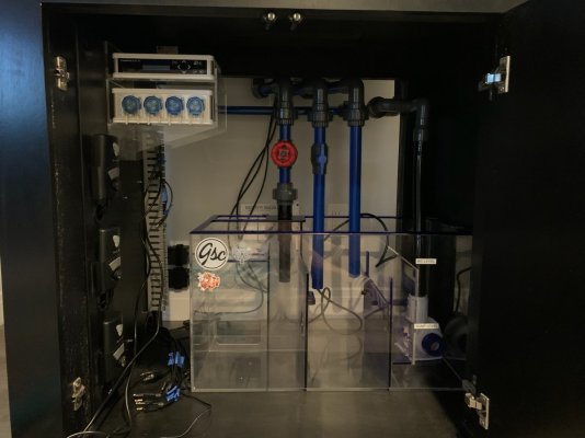
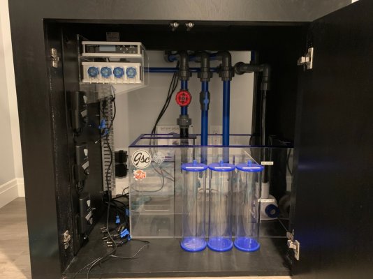
Current state of the sump area where all the stuff is still in the works. Soon the skimmer will be updated, and a few other pieces of equipment added.

7CAF2087-01AB-4B12-853F-76BE76618524.jpeg


Here's a picture of the inhabitants now of the tank! I have the Cherry Wrasse, Purple Firefish, and Yellow Tang which were all successfully relocated from the small tank to this one.

72276CE8-DD11-4E6F-A95B-1C3D476A44E9.jpeg


7CF12FF5-C37A-4ED3-BCDD-CAF903678663.jpeg
 
Last edited:
OP
OP
ilyad

ilyad

Active Member
View Badges
Joined
Dec 19, 2011
Messages
490
Reaction score
610
Location
North Hollywood, CA
Rating - 0%
0   0   0
Another issue with running two tanks simultaneously is making sure that the core components are dosed accordingly. Luckily from my previous nice pick up of the used 4 bay doser, I have two which I can run. Wanting to save on some bucks, I decided to go the DIY route for the containers.

For this build we start out with the VOSS brand water bottle made out of glass.

468641B7-150F-42D9-9919-D249989B7D27.jpeg


Remove stickers

45B83176-ED43-411D-800C-FF519BD3A958.jpeg


Although not necessary, the stepper drill bit helps you get very clean cuts to various sizes.

F6FA3A2C-FB52-4052-826D-9E43374C7CE8.jpeg


Measuring the size of the opening

2BA4D547-DDAB-4E83-8705-55B3C449C562.jpeg


Cut the cap with the bit.

31C062A8-6DC9-437A-B088-0C1E6E6B3600.jpeg


The fit was perfect for this part.

8237C82D-3C09-463F-A890-17133757C16E.jpeg


Unfortunately, the small bulkheads sold on BRS are either wider, or the glass bottle design was changed because the tightening lock (although fits), interferes with the glass bottle threading to get a closed cap.

E3DC9783-C707-4101-AD15-5DBF646980EE.jpeg


E5C9F593-43B3-4CAA-BAE0-F5896BFFBB9C.jpeg


90715433-8C1B-4D36-9E82-557E2DD75477.jpeg


After a bit of head scratching, I decided to test the bulkhead sitting on the glass and then tightened down by the cap. I had to open the hole a bit wider for that.

E0873B5D-3A0D-4860-A8B0-58780D7C5DC1.jpeg


FDD9F9BF-75BC-43A6-8772-4B41851880C6.jpeg


Now that the lid closes tightly, I had to make sure that air can draw into the container. Otherwise, you have a building of pressure and eventually two part would not draw. For this I used the tiniest drill bit and added small holes. Originally, I added only 1 but then put 1 more in the event one clogs.

8A78898F-B569-449F-8939-3CD6DAFC2DCC.jpeg


B2B76AAF-3B3B-4D96-B47C-8E68F364643B.jpeg


Here is the finished product now.

85455D11-6D0D-46E4-B254-94F51A72E0EC.jpeg


I am adding the parts list here too so that people can look into this if they wish:

Supplies:
- Voss water bottle - $2 (at your local grocery store)
- Push Connect Bulkhead - $4 (BRS)
- Stem Connector - $1.50 (BRS, this is not absolutely necessary but makes the connection better for less leaks)
- Acrylic Tube - $1.25 (BRS, $2,50 foe entire tube but each of these should be enough to make two containers)
Note: these are the parts I purchased, as often the case, bulkhead, connector, and tube can all be sourced cheaper on eBay or Amazon most likely)

Tools (these are useful, but not necessary)
- Tube Cutter - $6 (BRS, this allows you to get a very clean cut on the tubes)
- Stepper Drill Bit - $39 (Home Depot, this is by far the most convenient tool, but completely not necessary as you can use big drill bits, cheaper stepper drill bit, or even a box cutter and some sand paper after to even out the cuts).
 
Last edited:
OP
OP
ilyad

ilyad

Active Member
View Badges
Joined
Dec 19, 2011
Messages
490
Reaction score
610
Location
North Hollywood, CA
Rating - 0%
0   0   0
Ok, I have more updates, if anyone is still following this snail paced build.

First and foremost, the thermostat on the nano chiller crapped out... so it was time to get a new one. Having been keeping my eye on smaller alternatives to free up some room, I decided to go with the Chill Solutions chiller. Its pretty snazzy looking and easy to hook up.

IMG_8884.JPG


IMG_8883.JPG


And how it looks tubed up.

IMG_8885.jpg


Next step was to get the previously made dosing containers hooked up. Here you can see the tube being attached to the barb and then zip-tied for security.

IMG_8887.JPG


They fit quite nicely in the sum area... actually making it easier for me to see the container amounts now that they can be stacked side by side instead of in a row.

IMG_8892.JPG


And a little close up.

IMG_8894.jpg


Next, we have to free up the XR15 that is on the nano so that it can be moved to the 75 gallon. Again, in my efforts to streamline the nano, I have gone with a slightly smaller light, the AI Prime HD along with the gooseneck.

IMG_8902.JPG


I quite like the light as it comes with handy clips for wire management and is quite small in profile.

IMG_8951.JPG


IMG_8952.JPG


IMG_8953.JPG


After some tinkering with the channel levels and using my PAR meter, I was able to dial in the AI Prime to have roughly the same PAR and color scheme as the schedule previously on the tank.

IMG_8956.PNG


IMG_8957.PNG


The next day, all the corals are looking like they are enjoying the light very well... I think they are even more plump than under the Radions.

IMG_8973.JPG


As a side note... I am still trying to catch the last fish using a fish trap, but it has gotten too clever having seen all the other ones pulled out that method. Still no luck with getting it out. I have purchased the Tank Matez bubble trap which should be here next week to try and see if I can fool the fish that way.

IMG_8918.JPG


The fish will look at the trap and just wait by the door until the fish food eventually floats out. I have spent too many hours "fishing."

IMG_8917.jpg


However, the fish that were caught, seem to be doing pretty well in the new tank... Here are just a few of them.

IMG_8911.JPG


IMG_8912.JPG
 
OP
OP
ilyad

ilyad

Active Member
View Badges
Joined
Dec 19, 2011
Messages
490
Reaction score
610
Location
North Hollywood, CA
Rating - 0%
0   0   0
In this installment, I continued to add more equipment to the aquarium... some new, some which was freed up from the nano.

First, lets start with a new skimmer! The old one just didn't not pull gunk for some reason, and always created too many micro bubbles. So I went ahead and got myself a Nyos 120 skimmer.

IMG_8938.JPG


IMG_8939.JPG


Here are the parts that come in the box, requiring some minor assembly.

IMG_8940.JPG


One of the steps is to remove the skimmer body to put the pump and the diffuser plate inside. One cool feature are these little separate body holders. The smart part of this is that if you accidentally over tighten the screws, you only risk breaking these clips (which I assume can be replaced) instead of the entire skimmer body.

IMG_8941.JPG


IMG_8942.JPG


Here is the skimmer fully assembled

IMG_8943.JPG


And right off the bat, has great foam bubbles!

IMG_8946.JPG


At the same time, I have moved over the dosing containers from the nano.

IMG_8947.JPG


Finally, I went ahead and removed the XR15 (which was replaced by the AI Prime HD).

IMG_8959.JPG


A quick wipe down of the light removed all the dust... and then attached the previously made brackets.

IMG_8960.JPG


IMG_8961.JPG


IMG_8962.JPG


Then I taped the power cable to the feed string and pulled the power cable through the wall.

IMG_8963.JPG


The light in its place

IMG_8964.JPG


Cool view of all the lights

IMG_8969.JPG


And a little comparison of the lights with only 1 versus 2 XR15s.

IMG_8967.JPG


IMG_8968.JPG


Finally, a little update video of the inhabitants enjoying some extra light now.

 
OP
OP
ilyad

ilyad

Active Member
View Badges
Joined
Dec 19, 2011
Messages
490
Reaction score
610
Location
North Hollywood, CA
Rating - 0%
0   0   0
Its been quite a while since I've updated this thread, but I have a good amount of updates to finally update here. Instead of spreading them out over time, I will go ahead and get this updated as close to today as possible.

First to some DIY activities...

Instead of running socks, I always try to run filter floss in my tanks so that the maintenance is quick by just throwing out the filter floss instead of washing socks. Because who has time for that?

Here is the problem I am facing - the flow eventually turning up the filter floss and creating a passage where water can flow past the filter.

A24D6839-976F-4E1D-BD9B-630199B31830.jpeg


To combat the issue, I have decided to create an acrylic tray with holes in it that will sit over the filter floss. To make sure that enough flow passes, this will require a ton of holes.

First, I took a small extra piece to test on and cut it out, marked it off into 1/2 inch squares, and drilled a few pilot holes.

B408DF7C-0B3C-4333-A0CD-CC16CB6EA37A.jpeg

20BA1A06-E35E-472C-B379-D85BE5FD390A.jpeg

088BCA3B-E0D5-43F7-94F7-07E67631566D.jpeg


After being satisfied with the sample piece, I cut a piece to exact size and marked it off.

1E22D266-4325-4049-9DAF-756668FB872F.jpeg


Added all pilot holes

5D4E411B-3F9B-49BB-9AD0-7CD1BF3FCCB4.jpeg


And using a step drill bit, started to cut the holes.

9EFDDD6A-AFB1-4905-8E79-CAEE18A315DF.jpeg


Here is the entire cover drilled out.

8AE816D0-C319-444F-A13F-F632EB327E97.jpeg


All the extra acrylic that was drilled out.

4FEF84E1-5087-45A9-9E65-161B972A0B27.jpeg


And how it looks with the protective tape off. You can see that there is a lot of residue left because the acrylic was old and laying in the garage for years.

62210E56-E70E-4435-A0DD-7934175004C9.jpeg


And here is the clean version.

463061D6-AB3D-4F5E-A8A7-BEE49102E369.jpeg


This is how the cover works to hold down the filter floss in place.

30B3062E-F374-4014-99C3-2317377EF235.jpeg


Quite happy with the result... as you can see, a lot of gunk picked up and can easily be replaced.

44EB52E5-D7B5-4B83-A420-C291622B4E6D.jpeg
 
Last edited:
OP
OP
ilyad

ilyad

Active Member
View Badges
Joined
Dec 19, 2011
Messages
490
Reaction score
610
Location
North Hollywood, CA
Rating - 0%
0   0   0
Continuing on with the build update, did some more sump optimization and DIY'ing.

First, since I purchased the doser used, I wanted to refresh the product with the maintance kit and new tubing which changes the rollers, holder, tubing, and the roller covers.

9A8A394E-6711-4DFA-8FE1-7255CEB128DF.jpeg

1E5E32E4-CB3A-4605-A91F-32022B500322.jpeg


By removing a few screws, you have access to the parts to remove.

AD201D12-25AA-4DDF-B4F6-20554EEAA274.jpeg


Here are the parts that were replaced.

5A898B0E-2D80-4FCF-824E-136E29102066.jpeg

6DB68612-11C1-46CD-BCD8-14C778140AE8.jpeg


And a quick comparison of the old versus new tubing.

D2791E15-52BE-479C-B0AC-681138905993.jpeg


Now the parts are replaced and doser is ready for use, plus the old replaced parts.

7361902A-FC70-4EC3-AEE7-3BFD0FF393C2.jpeg

F81666EB-E74C-446F-8B26-59490B7D51D2.jpeg


Second, and pretty easy step was running tubing for the dosing from the containers, to the doser, and towards the sump. After a calibration run, I was able to set the proper dosing levels for each pump.

6234E7FC-F7D6-4A3C-94CB-2C6305516C1D.jpeg


I also used the VCA tube clips to keep the dosing lines cleanly organized.

A0BF5FC3-F9E8-4C39-BBCC-5EE18ED78E30.jpeg


As previously mentioned, I intend to use one of the GHL doser pumps for my ATO refilling. This means that I needed to figure out a way to connect a feed tubing for that, meaning it needs to sit in the ATO container deep enough to feed the water.... when initially running just the tubing, I was having issues with it pulling out or bending. So the process was taking some spare parts and making a feed contraption. I took the dosing line and combined it with some remaining acrylic rods (from my previous DIY job), and the VCA tube clips.

403B6986-D325-4855-BBB6-2402C0332EBB.jpeg

954582BC-27A7-4819-92EC-E65422348317.jpeg

B09145CE-D427-4B38-8534-10A03024F7F0.jpeg


I then used a few zip ties to keep it held in place even better. Note that the dosing tube is slightly higher than the ends of the rods to make sure the tube does not get blocked by getting stuck to the glass.

3D124C90-A7FD-43FC-9961-0F0E6904A94C.jpeg


And then this is how it sits in the ATO reservoir. The acrylic rods keep the feed tube straight and weighs it down to the bottom of the reservoir.

9242FDCE-7E8E-4DF4-A807-22AD0356947E.jpeg


Lastly, one of the tricks I always utilize for dosing 2 part is using a small Y connector and merge the Alk and RO lines together. The purpose of this, is to make sure that the alk line never hardens and blocks. This ensures that that alk is flushed out and the tubing is clear for very consistent dosing. Using this method on my nano tank, I have never had to clear the tubing in approximately 2 years.

1C48E364-AD01-4A34-B7D7-F83AAD43D66C.jpeg

6CD930A5-D247-4D35-933D-18BF96D68A5D.jpeg

0D8D7515-B298-4A1C-8885-446D274C9FE0.jpeg


As a side note, I also organized the probe cables by pulling them out straight, zip tying them together and covering with a cord sleeve. This allows me to keep all those cables organized neatly as they run through the cable channels in the stand.

ECE7B5D5-6F15-44FC-B518-C178960D7D5E.jpeg

773F7CE3-AF3B-4D2F-B0E7-EAADBAD9F6E3.jpeg
 
Last edited:
OP
OP
ilyad

ilyad

Active Member
View Badges
Joined
Dec 19, 2011
Messages
490
Reaction score
610
Location
North Hollywood, CA
Rating - 0%
0   0   0
It has been quite a bit of time since my last update. Lots of new life events happened that kept me from updating this tread. Since last time, I purchased a home, went through a full renovation, got married, and got a puppy.

That all being said, I have moved my aquarium and set it up in the new place. In the next few days, I'll be doing some updates here to show the current progress.
 
OP
OP
ilyad

ilyad

Active Member
View Badges
Joined
Dec 19, 2011
Messages
490
Reaction score
610
Location
North Hollywood, CA
Rating - 0%
0   0   0
Well, here we go! Its time for the updates to begin. I have quite a lot, so I will try to update over the next few days.

As seen previously, the floating canopy design was attached to the wall on the previous build. Continuing in the same fashion, I intended to do the same in the new place. However, because I knew that, while renovating, I installed wooden reinforcement between the studs inside the wall prior to closing and painting everything.

016ab0004a5bd15605ce1e75fd5f375a998b3ac614.jpg


And since the tank would not be set up until much later when the renovation is complete, I measured the location of the reinforcement for quicker reference during the build.

0114bfe394160f5febf42a4a171464faef4c480779.jpg


01367ce1278486d0e6a1bbaab9ba52a21d112293e8.jpg


After giving it some thought, I also made the decision to upgrade the tank! Unfortunately, I could not go bigger than the previous 36x24 footprint, however, I ordered a new tank that had an external overflow (which did return some space inside the tank). While upgrading, I also purchased some upgrades for durability by adding corner braces, bottom bracing, and a starboard bottom.

New tank delivered to my LFS

01e7a5fa5871a46930e1cd9e6f0a37892598e96168.jpg


And here it is in my living room, where it sat for roughly 2 months before I had a chance to finally start putting everything together.

01d912fcce46e5d46baad40090968aa42562b56fd1.jpg


Old tank was broken down, and all livestock moved to my LFS (Big shoutout to Elliot at @ Golden State Corals for letting me keep my fish and coral there during the move and all his help in getting set up!)

01899907a4d15a456b5ede021053489b98139b8ebf.jpg


All the equipment that was being moved from the old tank to the new Knowing I was going to be moving sometime during the life of the tank, I designed the canopy and the gear to be easily removed and transferred, and the design worked!

01dfd10b1e0a81c95572fbe410da17cc4f13ab3312.jpg
 
OP
OP
ilyad

ilyad

Active Member
View Badges
Joined
Dec 19, 2011
Messages
490
Reaction score
610
Location
North Hollywood, CA
Rating - 0%
0   0   0
Why not do another update, that has a bit more substance...

Since the new tank now has an external overflow, all of the plumbing had to be redone!

First and foremost, since there is now two separate return outlets (previously one outlet running a Y), I wanted to make sure I can control the flow for each independently, in case I would like to adjust one or even them out. Also, without an internal overflow, I needed to put in check valves to reduce how much water goes into the sump.

Here is a mock of the return fittings.

012e96a7eeb1b1b3a6521475c434e0e92076feed74.jpg


And here is the back of the tank with the initial stages of overflow and final connections of the returns. For the overflow, the unions were offset to allow my fingers to fit in case they need to be undone.

012225a874e7ebde4c8db9fbc8aa238e374204421f.jpg


Then came the plumbing palooza... again, with Elliot's help, we got all the plumbing installed. Plenty of unions and points where things can be disassembled for redoing the plumbing or cleaning (future updates will show that paid off extremely well).

014af8fb11358a34db30813e0220e332af46b29a97.jpg


As you can see, the whole house was a mess with things all over the place.

And here is the final product... showing how everything is plumbed in together.

016fda7af796c76117a88d1bb362f32c5053e0d5da.jpg


01dc8db983e8c9e6e2dceb1b00cbf8bb066cb01c30.jpg


On the inside, the overflow plumbing is as follows:
- far left - main overflow using gate valve for fine tuning
- middle - secondary overflow using ball valve (since this only has minimal flow through it, saved on the space and $ by going with the ball valve). This overflow is submerged in sump water
- far right - emergency drain, as always with no valves of any kind and ending above sump water lever to alert any problems.

013e5b08ceec69fa394db512147bacb936b5f1217b.jpg


If you recall, on the previous plumbing I had a manifold which is now gone. It was removed because for the previous build, I never ended up using in a few years and needed the opening for all the overflow tubes.

More updates will be coming so check back often.
 
OP
OP
ilyad

ilyad

Active Member
View Badges
Joined
Dec 19, 2011
Messages
490
Reaction score
610
Location
North Hollywood, CA
Rating - 0%
0   0   0
After the plumbing was completed, some of the other components went in...

Outlet relocated to the outside of the tank stand for easier access.

01969fdfc0d6f6ed63e26527eeae98e034b06779fd.jpg


Canopy arm attached to the wall

011e361113f434618edb5ac794beae54b036278e72.jpg


Radion cables ran through the wall and brackets attached again.

01203be6b8199d672c2c45dddbe0a2f2a00f619110.jpg


01fdc64a1b9f29674caa9d1167f9d947d8277b42c3.jpg


Stand and ATO container placed in their spots

01b06434d507fc3803450dd6cd7621270ad386c22e.jpg


Quick check that the lights work

01b1c8c06d32c096bce1b7c4717381f397196a7eae.jpg


Tank was then placed on the stand and leveled.

016e739c48f3e8e5e21a8e09b961ede9823f098d18.jpg


And again, a quick check or both the Radions and T5s, with everything in place

0183f7e895becc0b6ffce5c9d3ab1d2e6fd9efb72d.jpg


Finally, the return pump hooked up to the plumbing

01fb5803016299dc80dd289a6e63f8657931aee960.jpg


And here it is! Finally, after almost a year of being taken down, and a full renovation later, the tank was finally plumbed and in its place.
01c7c178329fc5fc4842c3cacdd1ac16f5e4462337.jpg


0156eb2ade230f9ab0a12b5cbb6e13951be0fa8e71.jpg


Personally, I think this is the perfect size and place for this location. It was meant to be and has good viewing angles from a lot of the living space. It is also the first thing anyone sees when they visit as its right across from the main door.
 

NanoJHB

Active Member
View Badges
Joined
Apr 16, 2021
Messages
252
Reaction score
372
Location
South Africa
Rating - 0%
0   0   0
Sheesh what a read !

Love all the detail and effort that went into this build/s.
Really looking forward to finally seeing it stocked and running !
 
OP
OP
ilyad

ilyad

Active Member
View Badges
Joined
Dec 19, 2011
Messages
490
Reaction score
610
Location
North Hollywood, CA
Rating - 0%
0   0   0
Sheesh what a read !

Love all the detail and effort that went into this build/s.
Really looking forward to finally seeing it stocked and running !

Thank you NanoJHB, glad you enjoyed the detail and for following along my journey. There's more updates coming soon... It has been a long road with some pauses and quite a lot of DIY, but all are totally worth it!
 
OP
OP
ilyad

ilyad

Active Member
View Badges
Joined
Dec 19, 2011
Messages
490
Reaction score
610
Location
North Hollywood, CA
Rating - 0%
0   0   0
The first time the tank was set up, with too little space on the sides of the stands, the GHL Touch was not mounted for easier access. However, with plenty of room, it was time to get it set up on the stand.

First step was figuring out where the reinforced wood was on the interior of the stand and marking the exterior with blue tape.

014de21310b6078a4d504d4b5c6285747db4b60d77.jpg

01e1579d729145547a05a3ab88a4f1ababef76b6c6.jpg


Then a quick "test fit" to see how it would look.

017c3710463a88c257c90f938feb1079762782504d.jpg


After marking the vertical height, I marked off the depth.

012181447ee9b067e409dedf9355a7de4d3e9c76c3.jpg


0127418c2bac9d9e09275245297791f11fc22bca7f.jpg


Once again utilizing the paper trick (where a cut out was pressed with fingers to see the openings) I was able to get a mounting template.

0188d0885cb0b805a2438acb979a5937ba6e708d65.jpg


010138cef58c53a38e198a792dbd88e985837b93df.jpg


0189ac160b9866fde6ca78fba35dead5d9cd4f47e4.jpg


01e396e6c8a1d5d9c732cd68be67a03a52b1daebed.jpg


011249b335021c65512a267afd112a72d87e33a2ed.jpg


Then I marked the spots that would be drilled and where mounting screws would go.

01624c91bd03b9f861071033affcfd1f8e3ad5b4ad.jpg


0136728eda59284049140cad2a3446de3b8b36a0bb.jpg


Drilling of opening for the cable.

019c820b804a1603874a6a93cd1ad6ae10c5f32bc0.jpg


019179dd165daecbc4af13827910181852725206c1.jpg


And added the mounting screws

013395a2a2497670b5f008835339622069e8696cd3.jpg


The screen mounted to the stand.

01a1e3fc7541ee550f573a6edd0f749e000fc1b1dd.jpg


Quick look from farther away.

01e02e06a5d2091c894c1f1dee1e5b1ff0becd6be3.jpg


And the breakout box mounted on the inside of the stand.
01fefc050755b888b22c1a3404210b7b3ecaff6886.jpg
 
OP
OP
ilyad

ilyad

Active Member
View Badges
Joined
Dec 19, 2011
Messages
490
Reaction score
610
Location
North Hollywood, CA
Rating - 0%
0   0   0
Next step was to get all the electrical components put into place and tons of cable management.

First time the tank was set up, it was against a wall and capped with furniture and wall on both sides so a ton of wires just laying behind the stand were fine. In this new location, one side of the tank is very visible when going in and out of the bathroom that is located just to the right of the tank. So I needed to make sure all wires were neatly tucked and very minimally visible from the side.

As a reminder, this controller board had all of the power supplies mounted to the inner side. Lots of zip ties and wire guides.

011f12fb2e3337fdc4faa335fbc6e46af82445bb82.jpg


View with the controller board, Profilux and Doser (you can also see the tons of cables that will need to be attached). The Ecotech back up battery also installed on the wall.

0186bba895a8a9eed79138976455f26b2474b70db1.jpg


Starting with the Radion and T5 lighting, I routed the cables along the wall and used cable channels and wire holders. Wall mounted versions were white to match the trim. Radion power supplies also wall mounted using their holders.

012d18a0b707729d95da037163ebe5372472f870d3.jpg


01331a5666950457264c392ae86aeca0880e699a95.jpg


01dc8411f6f3d7a48c13d47936cdf49e95fd3a39b3.jpg


Also, to clean up all the loose cables near the outlets, more cable storage was added. All have been wall mounted using double sided tape (included in the wire management kit off of amazon).

01806339d5b6e53e643c1a7419a7acbdc6d7e7ae6c.jpg


012be46437058b0ec5176748c8175345ab7dc11c60.jpg


012dbdfc076933fcf9135be26a3f9accf480a87f62.jpg


010b42237d6cbe7aa0823773b06072d92215a3dfcd.jpg


For wire guides on the stand, a black version was purchased.

013f826edd78812129ede93aeb376246d75cbea995.jpg


I initially though about putting the guides vertically so that cables can come in and out easier.

01feffffda1c42ff6d4af1f5590b96c5887676c726.jpg


However, that idea was scrapped because of two reasons: First and foremost, any water spillage would possibly pool in those and that is not good. Second, the space would only allow me to put 2 guides.

In any case, went ahead and measured out the necessary lengths (2 of them were too long and stuck out past the sump, 1 was not long enough). After that, cuts were cleaned up with some sand paper.

01b4624477bfa3ca4d381ff3cce834573085cb496e.jpg


0131bcc04ca6dfd8fbb53bc7c2e7f1395d47ed8062.jpg


017e37c252fba2138fc5dd48693de0dc21f023c7e0.jpg


The solution was to stack them! This allowed me to put multiple levels and the channels would actually protect some of the water getting in in event of splashing.

01c96889239a87aeef69366fb91bfd88c24ecc7d92.jpg


Here you can see how the wires can enter.

015ef5d65a4d2a9830ff3c598f4467fd7c43f4622f.jpg


I used double sided tape again and stacked the number I needed.

01191e0689bae49e4719389c1537181a805db8e6dc.jpg


01f2e52459d35dc69b5996528faa11e8e7ef4db63c.jpg


Here is the look from behind the stand.

016504c2197ce2c434f244bf1a6b23e91e596f2324.jpg


GHL probes were grouped together, and you can see that they can still easily fit the channel.

015f2d2fad3a7b6c344b83ecd67a7cc46171593f8b.jpg


Since the probes did not have to go to the end of the sump, a third shorter channel was added.

0187aa0436c15a65954b9b2802e330908b05227bd1.jpg


012279b564aa6138967d9b5059c1f8c4c83d0fe27a.jpg


01bc5228d3f426a8c5b018d10bba30ef1050da2493.jpg


And the view of the space between the sump and the controller board.

01d90684f93aa3c882e7d786cc61574940b0d5ad79.jpg


Wires enter from the bottom of the wire manager and run up it to the controller, doser, and the outlets as needed.

01f1df6c5c82ac40e5647c6530a394d96119ee5929.jpg


To reduce wires from sticking up too high on the power strips, I used wire mount and zip ties to route the power plugs from the front strip.

01f32e5d10e4a159ede61a169ed947441a39c3adde.jpg


And since the power supplies were staggered initially, all the wires can run across without interfering.

0187d9aaa1170490195ac782e2181cf79c3e809ad1.jpg


And the final product. Here you can see the tank, and all the special areas.

0195a7be5fdddfec9363ec6aa551f0f01e7040e4e6.jpg


017e3bea3a705263c8faa4bf6a4fe5794ea72163bf.jpg


012fe799520d86625885c18416da8317d03795a881.jpg


0179aa2db9cd804c7402d969d24ac81ca1ea0dc4c6.jpg


01a7244fafcf6829aec4b8c5831992ab4ca34f6296.jpg


And most importantly, this is the view from the side (which was the main concern). Although its impossible to make wires fully invisible, its so minimal, I am ok with it.

010d28bce6223684342b4bfbccdf469af64002ab38.jpg
 

Attachments

  • 01706880bc3a4f8af27fd340883d0f7b3bd7d4abee.jpg
    01706880bc3a4f8af27fd340883d0f7b3bd7d4abee.jpg
    132.8 KB · Views: 35
  • 0186bba895a8a9eed79138976455f26b2474b70db1.jpg
    0186bba895a8a9eed79138976455f26b2474b70db1.jpg
    157.4 KB · Views: 33
  • 01706880bc3a4f8af27fd340883d0f7b3bd7d4abee.jpg
    01706880bc3a4f8af27fd340883d0f7b3bd7d4abee.jpg
    132.8 KB · Views: 34
OP
OP
ilyad

ilyad

Active Member
View Badges
Joined
Dec 19, 2011
Messages
490
Reaction score
610
Location
North Hollywood, CA
Rating - 0%
0   0   0
Shortly after all this wire management took place, the puppy we've been on a wait list for almost a year was ready to go home with us! For the next two months, the tank build came to a screeching halt as we had to train and get used to the pup. But I cant complain, just look at her cute face!

018475f9c553650eed793f43141062e83e144606fc.jpg


01b551d17280d2376bb00f7753783de1be0221a60a.jpg


018d9e49bc75d13ebcfb3a290bf16bbf91b5dfa65c.jpg
 
OP
OP
ilyad

ilyad

Active Member
View Badges
Joined
Dec 19, 2011
Messages
490
Reaction score
610
Location
North Hollywood, CA
Rating - 0%
0   0   0
Fast forward a few months, and I was able to complete some misc things connecting the rest of the equipment and the tank was finally wet again! Cycle began on Dec 7, 2021.

Here is the picture of the cloudy tank water from all the sand.

015b243c2053bc44d8858002807680fba94962cfa3.jpg


0190f02d1ef067a9ca81b8329208c42b495fe438b0.jpg


Next morning, the water already started to clear up

014586555a61463eed1cde08a655956954189ee594.jpg


And after a few days, looking great! (And puppy significantly bigger too)
011be54d36d0c51ae813067e4d50d22037dbaca0e8.jpg


And here are some shots of the tank in all its glory (equipment and all)

014c1e482ebb4f553144076b389ee1de89f3ed0388.jpg


012a23a45719cfd51186e093f590b459f5f3e021f9.jpg


016f44c6c8a47d0ae88a2ba280c1de5a9d7d3d8721.jpg


015665d9b348c15c04ef7353a67fd6e7e90feb47a2.jpg
 

Being sticky and staying connected: Have you used any reef-safe glue?

  • I have used reef safe glue.

    Votes: 135 88.2%
  • I haven’t used reef safe glue, but plan to in the future.

    Votes: 9 5.9%
  • I have no interest in using reef safe glue.

    Votes: 6 3.9%
  • Other.

    Votes: 3 2.0%
Back
Top