Question is on PH sensor cable length. Think about moving my Robo-Tank controller to different location any for my tank. How long of a cable can you use. I have been able to get temp sensor DS18B20 to work successfully 12ft away from controller with dropping signal, but that required going to a 12 gauge extension cable. I need to extend temp sensor and pca9865 cables.
Navigation
Install the app
How to install the app on iOS
Follow along with the video below to see how to install our site as a web app on your home screen.
Note: This feature may not be available in some browsers.
More options
You are using an out of date browser. It may not display this or other websites correctly.
You should upgrade or use an alternative browser.
You should upgrade or use an alternative browser.
Another PH question
- Thread starter Wolfw28
- Start date
- Tagged users None
Whooo, good question.
A thing to keep in mind here: pH probes and the DS18B20 Temperature sensor work differently.
A thing to keep in mind here: pH probes and the DS18B20 Temperature sensor work differently.
- pH probes provide a voltage source
- the sensor on the other end has a very, very high resistance so it can read the voltage without currents
- in Theory you can increase the cable length indefinitely
- in Practice you increase electrical disturbance effects on the wire
- Personal opinion: should work fine, just watch that the signal stays stable and on the same level when you extend vs not extend
- unnecessary details:
- you have some innate protection in the coax wire, since you measure a voltage difference, any disturbance will most likely distub both core and shield equally, so the difference stays constant
- improved shielding would require a double shielded coaxial wire, so voltage signal in the core relative to voltage signal on the first shield, all shielded by the outer shield.
- the DS18B20 Temperature sensor is a probe and sensor in one that is connected to a BUS line and VCC and GND
- In Theory:
- The sensor needs a minimum VCC @ well below 1mA
- the cable resistance will supply this <1mA not at full VCC
- This gives an upper limit to cable resistance and therefore length
- The sensor needs to pull the BUS line to below 0.7V and back above to VCC within a certain timeframe for the protocol to work
- the cable-capacitance needs to be dis- and re-charged to do so
- this also gives an upper limit to cable capacitance and therefore, length
- The sensor needs a minimum VCC @ well below 1mA
- In Practice:
- <1mA is basically nothing, so no concern there
- you would need a resistance (cable+contacts) of >1k Ohm to drop 1V
- for 1k resistance you would need to screw something up pretty badly ^^
- also: 1V loss in VCC might not be enough to disturb the sensor
- the cable-capacitance is more important
- here is someone who had a problem with 15ft, but was able to solve that by using a different wire
- other people report using the sensors at 200m or so, using Ethernet cables and lower pull-up values (minimum of 850 Ohm according to somebody)
- so 10-20m or so should be absolutely doable, using the right cable
- some people report successful usage of Cat6 Ethernet cables.
- <1mA is basically nothing, so no concern there
- In Theory:
- The PCA9685 PWM lines are maybe more tricky
- they have a limited current of ~20mA (inline 220 Ohm resistor)
- I would recommend testing a CAT6 Ethernet cable as well
- you should probably use a twisted pair as combined signal+GND
- this gives you 4 pairs per RJ45 connector, so 4 PWM lines
- testing is difficult however, since the change would probably be most visible on an oscilloscope
- if that shows problems you will most likely need a Push-Pull circuit to increase the current limit on the PWM signal
- What do you need the PWM signal for ?
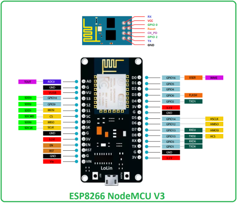
We’ll I kinda got the extended Ds18b20 and the pca9865 problem solved using NodeMCU/ESP8226
With 13 GPIO pins flashed with Tasmota and another problem because Reefpi only supports control of 1 pin per device in Tasmota driver. I plan on buying and moving up to a ESP32 which has

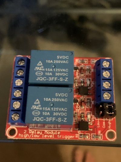
25 GPIO pin and Flash it with Tasmota not that both board have uart pins and I2c pins a capability that Tasmota can use and make accessible using MQTT and web connect. It’s to bad that the author of Reefpi doesn’t seem to care about updating the Tasmota driver to take full advantage of this. The board are cheap under 12.00 us for extended wi-fi control of multiple devices. I’m currently working on a 4 outlet power bar for out side using a ESP8226 with 2 of these
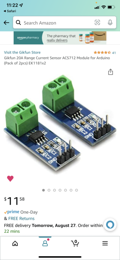
And 4 of these board for current monitoring love to tie them all into Reefpi. By the way your build is looking good. Question what do you do for a living.
With 13 GPIO pins
 flashed with Tasmota and another problem because Reefpi only supports control of 1 pin per device in Tasmota driver. I plan on buying and moving up to a ESP32 which has
25 GPIO pin and Flash it with Tasmota not that both board have uart pins and I2c pins a capability that Tasmota can use and make accessible using MQTT and web connect. It’s to bad that the author of Reefpi doesn’t seem to care about updating the Tasmota driver to take full advantage of this. The board are cheap under 12.00 us for extended wi-fi control of multiple devices. I’m currently working on a 4 outlet power bar for out side using a ESP8226 with 2 of these

And 4 of these board for current monitoring
 love to tie them all into Reefpi. By the way your build is looking good. Question what do you do for a living.
That would be kind of useful. Well, who knows. If you keep pushing this it might yet see the light of day(...) It’s to bad that the author of Reefpi doesn’t seem to care about updating the Tasmota driver to take full advantage of this. The board are cheap under 12.00 us for extended wi-fi control of multiple devices. (...)
Thanks a lot ! As you can read in my GitHub-page under Background, I'm a studied scientist. To be more specific: a physicist, so I have learned a lot of the basic Theory in mechanics, electronics, chemistry and programming, as you might have guessed from the overwhelming detail in my explanations ^^(...) By the way your build is looking good. Question what do you do for a living.
Similar threads
- Replies
- 7
- Views
- 452
- Price: 500
- Shipping Available
- Replies
- 6
- Views
- 614
- Price: 800
- Shipping Available
- Replies
- 6
- Views
- 458
- Replies
- 24
- Views
- 653
- Price: 1400
- Shipping Available
- Replies
- 10
- Views
- 567
New Posts
-
-
Hello New to Saltwater; started 18gallon Nov2023 and 10gallon Dec2023
- Latest: DenverSaltyFarm
-
-
-


