

- Joined
- Jun 24, 2020
- Messages
- 601
- Reaction score
- 131
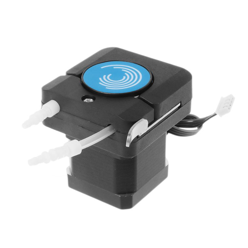
Any working and tested dosing part for nema17 stepper motor ?
I've found multiple projects, printed a couple of them, but there are many drawkbacks:
- A LOT of hours to print
- the one i've printed prints in 1 hour but the water goes back every time the motor stops making it totally unrealiable
- most of them are designed for hoses different than 4 ID / 6 OD mm , like the standard areator hose.
Any working project for a pump that doesn't have that flaws ? Even better if without steel bearing (3d printed would be ok)
I need something easy to print without tons of parts
As most of them require many hours to print and maybe some hardware to buy , i would like to know which one is better (and tested) to not trash aways hours, filament and hardware


")