GleamRail, the successor to LEDBrick

theatrus

Valuable Member
View Badges
Joined
Mar 26, 2016
Messages
1,955
Reaction score
3,355
Location
Sacramento, CA area
Rating - 0%
0   0   0
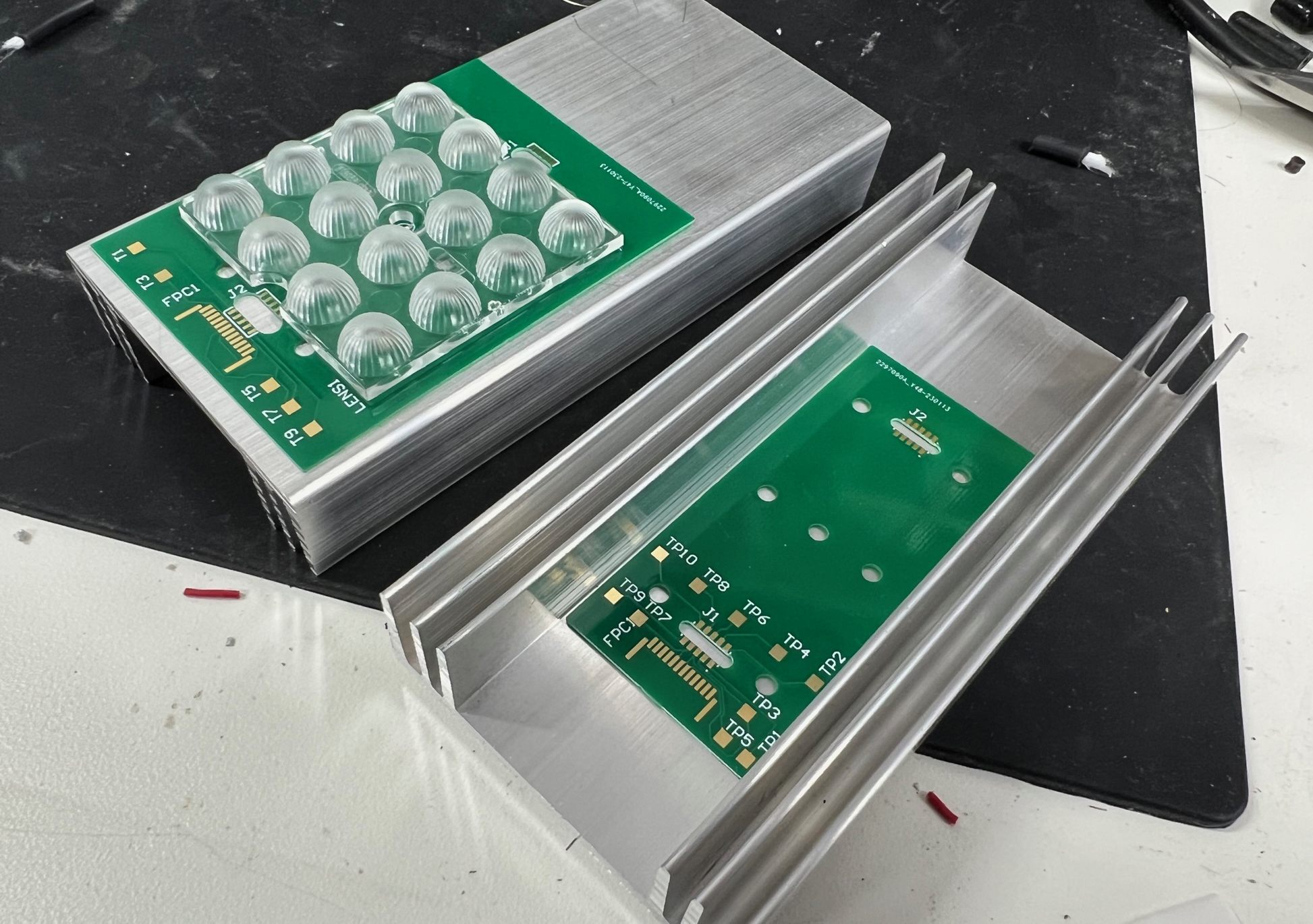
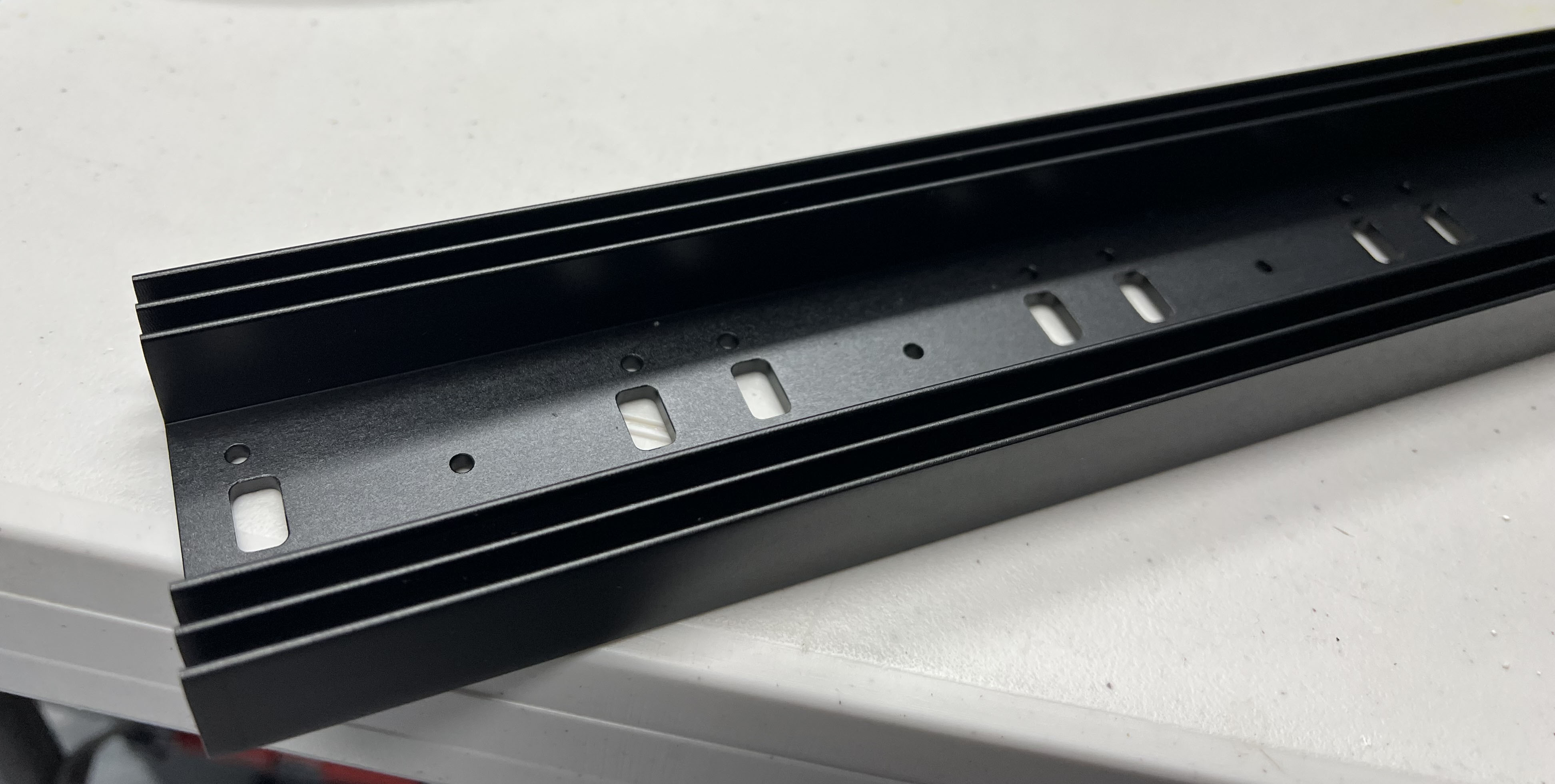
Status: Heatsink with machining work (alternate) received. First driver/LED pair build and tested. PCB layout and design continues.

run2.jpg


stackup_render.png


Hi everyone!

You may remember me from past threads including LEDBrick (LEDS! In Brick form! With no actual bricks!) and a few bad attempts at getting another reef aquarium started (Phoenix). Why not combine multiple projects in need of some refresh, and also try to knock out lighting for a new aquarium?

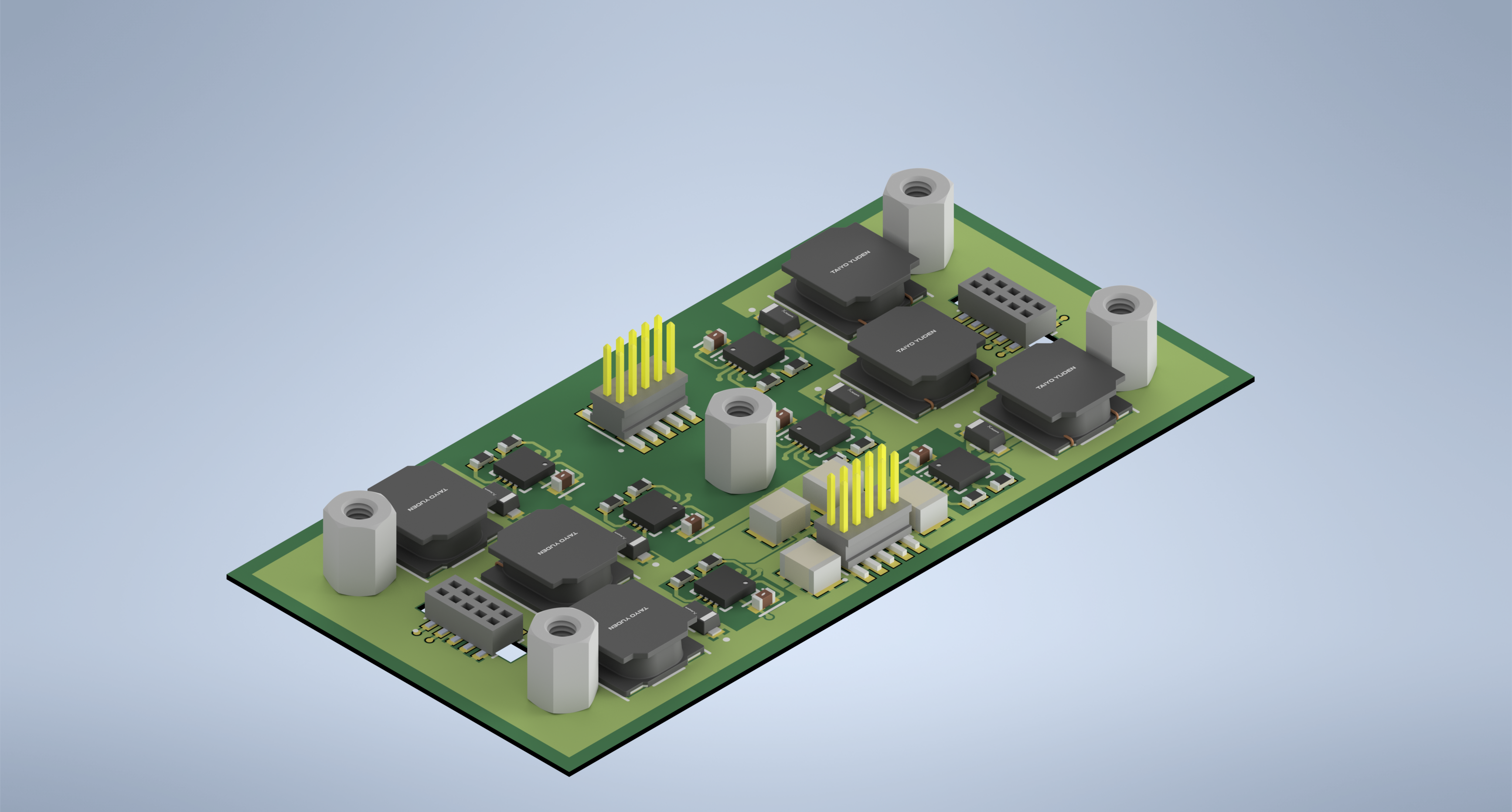
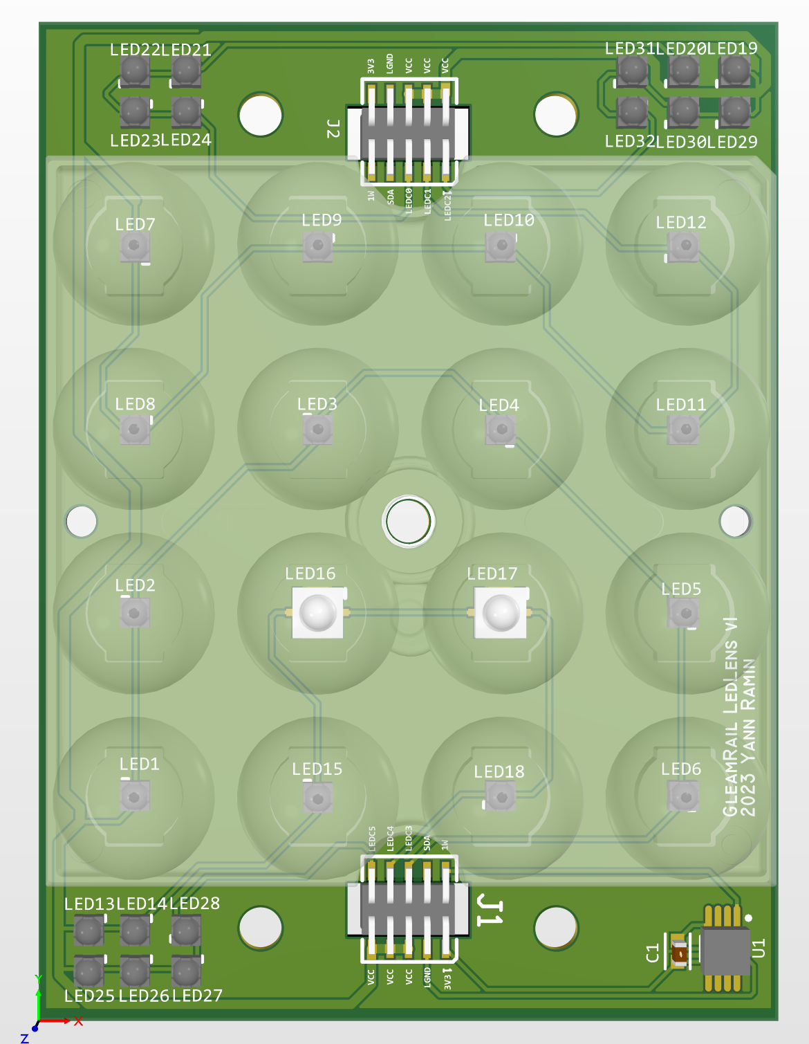
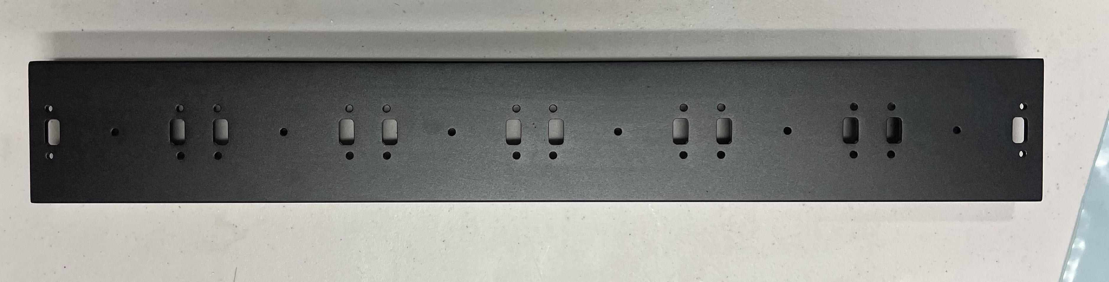
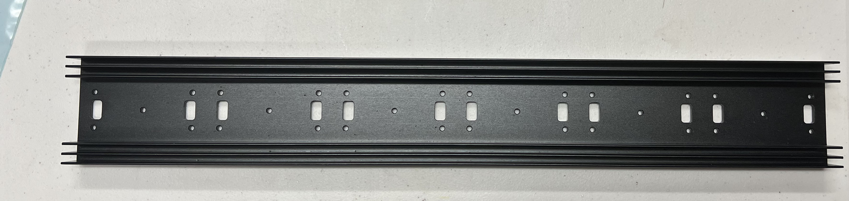
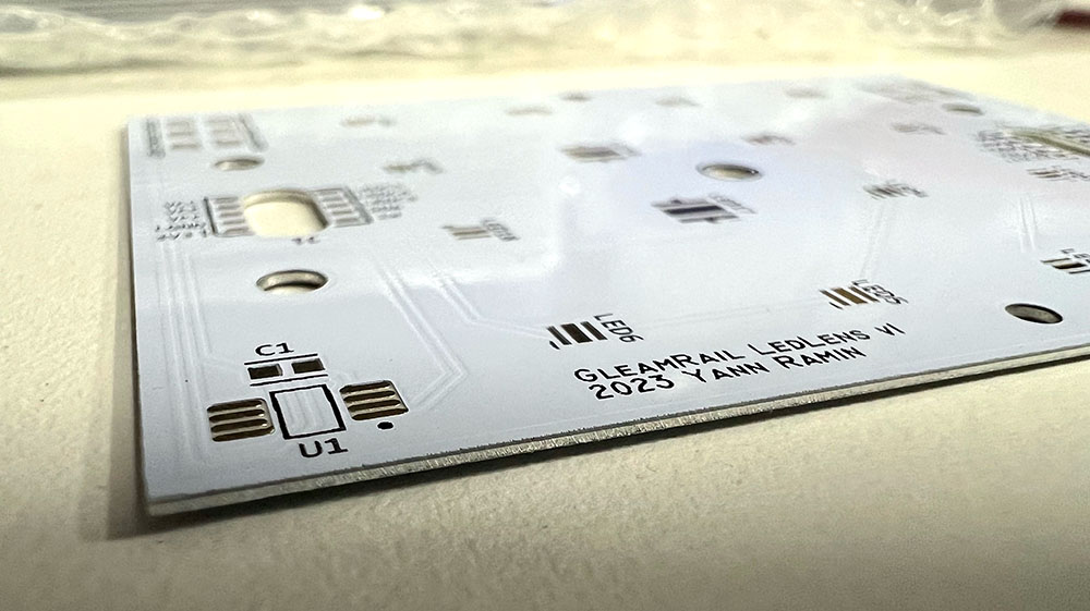
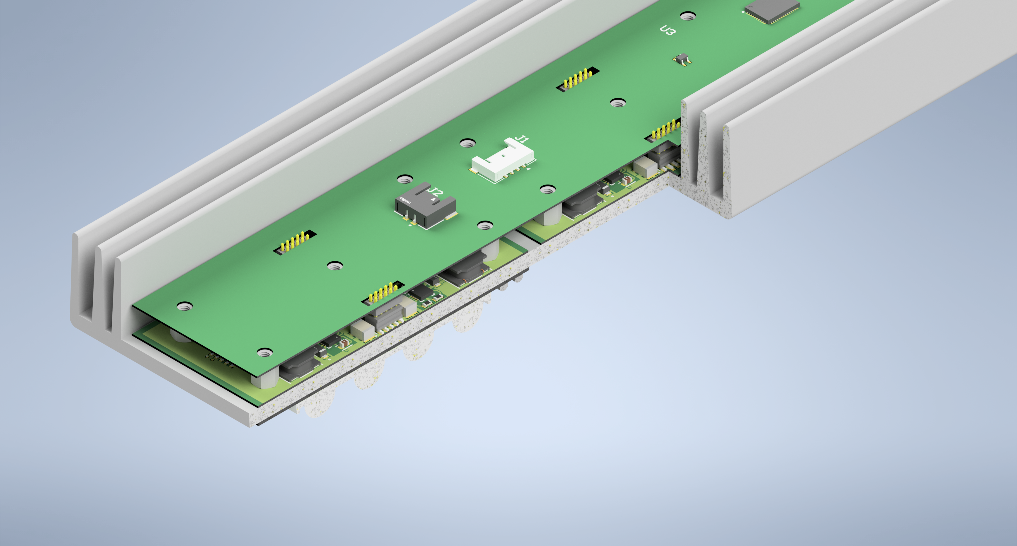
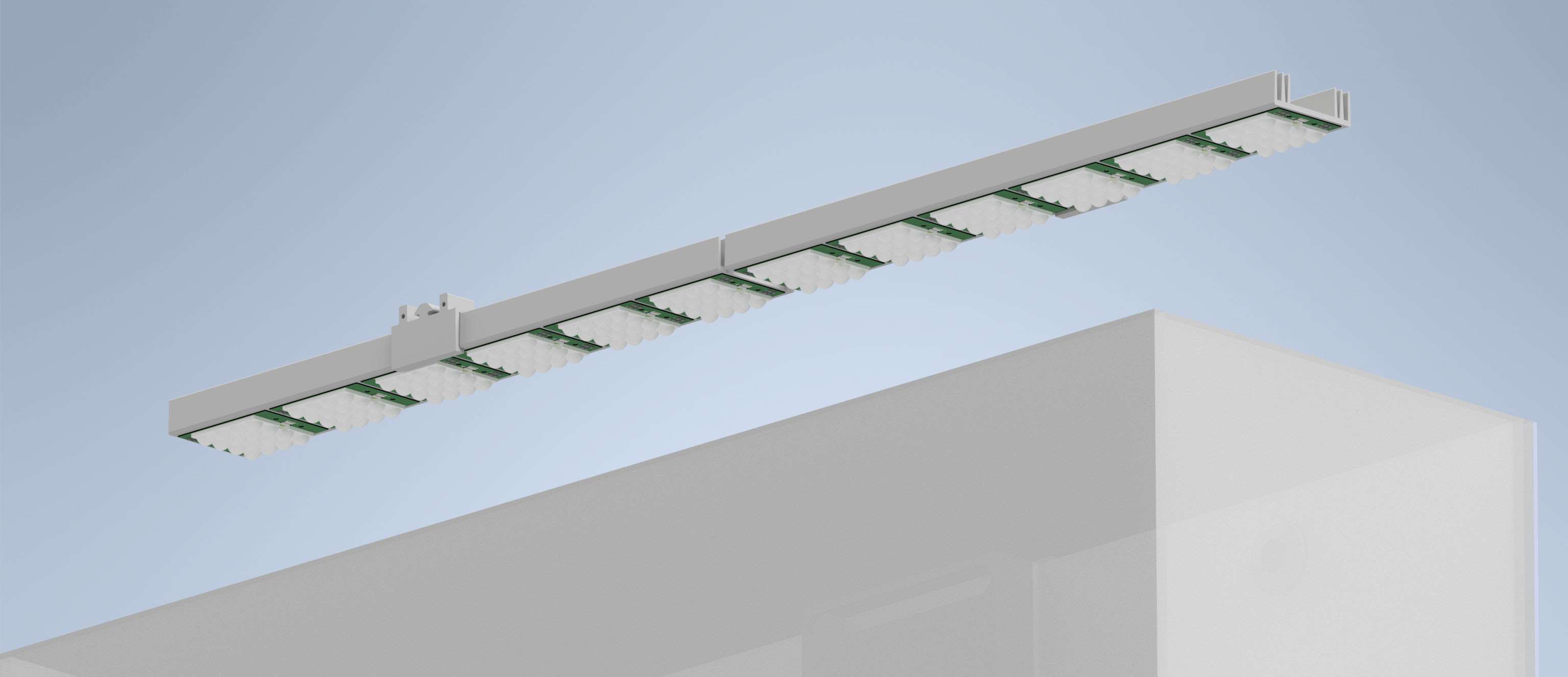
Introducing, the GleamRail. Concept art, without any shrouds, hardware, rails, etc below.

_Check_AquariumTwoHeatsinks.jpg


I wanted to try something different from just putting two pucks on top of the 22g long (36") tank, and also something different from just using a linear strips of lower power LEDs.

One of the challenges I've frequently had in my 90 gallon system with using four pucks is shadowing, and more importantly, shadows which stay in exactly one spot day in and day out. The very large colonies I've had (and then got wiped by a STN event, sigh) all exhibited lots of issues with one axis being the pretty one, and the rest atrophying away. Even adding T5 supplements (which I do), you lose a lot of the shimmer which actually is pleasing in a direct LED system. So, what would you do?

Option one is physically move the light source to mimic the sun actually arcing through the sky. However, I like things to be reliable, and putting some heavy LEDs on a linear sled, sitting above a wet evaporating box of salt water, and then reliably moving them back and forth day in and day out is about the least reliable thing I can think of. And this is the person who didn't seal any of the electronics in the LEDbrick and had to rescue them from moisture recently... maybe I too make terrible mistakes.

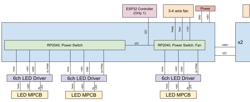
Option two is add _lots_ of LEDs, but only drive parts of them at nearly full power, effectively digitally fading the peak power across the linear strip as the day progresses. This means you need lots of high power LEDs (not super cheap) and the corresponding drivers or segmented power setup. You don't get as "fine grained" of a movement as physically moving the LEDs – its more digital than analog as light will only come from defined angles.

I'm building option 2 for the Gleam Rail concept. I've done a decent chunk of the modeling and pre-work to see if this is viable, so this post series will be build-log of sorts, going from some mock up and concepts, to design files, and actual building. Maybe I'll be done by mid-year (haha).

I'm going to leave some space for FAQs here, as well as links into the thread for future archaeologists.

Links

FAQ

How much will this cost?

Many dollars. I could probably buy a bunch of commercial fixtures for what this will cost end to end. Some of it is buying parts for replacements. Some of it will be wasted in approaches that don't work. Some of it will be spent in tooling I may literally never reuse, or could remotely justify the ROI on.

Will this fix all the coral shading problems and [ magical growth multiplier of acros ]?

No clue, nor am I building a control tank with the same flow, shape, corals, etc. This is not a controlled study, but at the very least I hope it doesn't make the problem worse. Maybe this is a solution in search of a problem. Doesn't matter. It'll look cool and grow coral.

Wouldn't the linear motion idea save money?

Probably would be cheaper. I'm putting 6x as many LEDs, drivers, and PWM signals into this. But then I won't have to listen to a motor or linear actuator ticking around all day long, or making concerning noises as the salt spray eats every mechanical part. Except fans. I'll be listening to them shredding their bearings about once a year .

Can you send me plans to build it and walk me through it? Can I buy one?

I'm happy to answer questions, take inspiration, and have discussions, but this isn't a design that’s going to be splashed together with some LDD drivers and an Arduino (though it could be with adaption! That however, is left as an exercise for the reader). Custom PCBs, machined heat sinks, 3d printed mechanics, and more. I'll be posting design files, firmware, notes, and so on, but realistically it is not your first-DIY-light project. I'm not interested in selling it, as I honestly don't think there is a market (been there, did LEDs for awhile).

Why?

Why not. This is fun.
 
Last edited:
OP
OP
theatrus

theatrus

Valuable Member
View Badges
Joined
Mar 26, 2016
Messages
1,955
Reaction score
3,355
Location
Sacramento, CA area
Rating - 0%
0   0   0
One of the things I look for when building anything is trying to find constraints to work under. While I can try to "free form" everything from nothing and go fully custom, its easier to build an LED fixture out of one of its most critical elements: the heat sink or other thermal solution.

I had envisioned some other past crazy ideas here, like using a very thin light and forming a water-jacket between the metal LED PCB, a spacer, and a top sheet of acrylic. Water cooling quickly entered "too many things that can go wrong" territory (coolant leaks, corrosion if you just use water were two major ones). If someone does want to try mocking up a water-cooled solution which makes the visible light fixture very slim, let me know since I did get decently far along with this. I'd advise using PC water cooling equipment (radiators and pumps) if you do go this route.

Since we're not water cooling, I went looking for existing extrusions for heat sinks which were both thin and narrow, but also offered something unique.

Enter the HeatsinkUSA (not a sponsor) 2.425"-wide extrusion:
2.425 Wide Extruded Aluminum Heatsink


This is interesting, since not only can you mount the LEDs on the bottom, you can also… mount all the electronics into the channel. You're missing surface area for any reliable passive cooling from convection, but fans are a sacrifice I was willing to make.

The first experiment in building this was validating how to actually connect the LEDs on the bottom to the drivers in the channel.

Enter Samtec (also not a sponsor) who happen to make pin-headers of just the right geometry if you're willing to violate some good common sense. Specifically, using the FTSH series pin header, but then… mount it upside down, mated through a slot cut in the heatsink, to a CLP bottom-entry receptacle on the driver board.

I made some (thin, 0.6mm each, which are needed to make the whole thing work height wise) PCBs with no function except slots and test traces, to validate the idea. Example time!

stack0.jpg


This is what I mean by mounting upside down:

stack3.jpg


Remember in a metal-core PCB, there is no bottom, as its resting against an aluminum heatsink. So, mount the header on the "top" of the board, just facing the "wrong" way.

And by magic… the whole thing mates through the thickness of the heatsink:

stack1.jpg


You'll also notice the test board has a 16-up Ledil Stradella lens on top of it - I'm going to test this lens setup, but no promises it will be used.

Next up: Mounting the rail to the aquarium, using 8020 uprights, followed by system architecture (6 LED boards, 3-6 driver boards, 2 PWM/power/fan control boards using an RP2040, and an ESP32 communication board, all x2).
 
OP
OP
theatrus

theatrus

Valuable Member
View Badges
Joined
Mar 26, 2016
Messages
1,955
Reaction score
3,355
Location
Sacramento, CA area
Rating - 0%
0   0   0
Lets talk about system structure now. One light, so one half of the tank lit in this case, is one complete module and runs totally independently, but can be synchronized over Wifi.

Lets break down what goes into the fixture:

  • 6x LED carriers/MPCB
    • TBD number of LEDs
    • 6 channels per board
    • Temperature sensor
    • These are the glowing bits, on a metal core board. Nothing too fancy.
  • 6x LED Drivers
    • Stacked on the other side of the heatsink to the LED carrier
    • 6 independent channels
    • Uses 6 individual LM3414 drivers, running at 500kHz
    • Routes power to the LED board, and passes through a 1wire signal for a temperature sensor
    • Accepts 6 PWM signals for dimming
  • 2x PWM and power controllers
    • Sits on top of 3 LED drivers
    • Provides all the PWM signals (18 each board)
    • Can turn on the power supply to each LED driver individually. This is to avoid glowing LEDs when the drivers are in the off state but some leakage still occurs.
    • Various power supplies to run from 48V (12V and 3.3V)
    • Controls a fan
    • Monitors temperature from each LED board
    • Routes power between all drivers, and accepts the input power from the external Meanwell power supply
    • Runs on 2x RP2040 (the Raspberry Pi MCU). Its cheap and has a bunch of PWM outputs, so its perfect
  • 1x ESP32-C3
    • Communicate with the outside world
    • Communicates with all 4 RP2040 controllers over I2C
    • Runs the scheduling and dimming decision.

The block diagram version is something like this:

system-diagram.png


This diagram shows half of a single fixture. Everything except the EPS32 repeats for the other side.

I've made some progress on the driver board and figuring out the mechanical alignment between all the boards. Here is a render of a nearly complete 6 channel driver:

driver_render.png


And a partially cut-away view of how all three boards stack together:

stackup_render.png


The LED board is captivated by the standoffs against the driver board with M2.5 screws.

Whats next? Making some LED boards, and starting the design of the PWM board.
 
OP
OP
theatrus

theatrus

Valuable Member
View Badges
Joined
Mar 26, 2016
Messages
1,955
Reaction score
3,355
Location
Sacramento, CA area
Rating - 0%
0   0   0
Working on the PCB layout for the LEDs. I've chosen to do a hybrid approach where most of the LEDs are stacked under the Ledil Stradella 16-up lens, but a few channels are _not_ under the lens for more diffuse lighting.

Each board has 32 LEDs now, which is 192 diodes for 17" of light fixture, or 384 for a 22 gallon long :anxious-face-with-sweat::anxious-face-with-sweat:.

led_pcb.png


led_sch.png


I've also ordered the heatsinks with machining work done from Heatsink USA.

Next up is the logic PCB.
 
OP
OP
theatrus

theatrus

Valuable Member
View Badges
Joined
Mar 26, 2016
Messages
1,955
Reaction score
3,355
Location
Sacramento, CA area
Rating - 0%
0   0   0
First bit of kit arrived: heatsinks. I ordered two sets of heatsinks, one using a machine shop through HeatsinkUSA, and one where I just gave the whole CAD file to a turnkey CNC outfit which machines the whole thing out of a solid chunk of aluminum. The... turnkey CNC operation shipped first. And black anodized it. Unfortunately, they also bead blasted it, which isn't ideal for a good heat sink surface. Oh well.

It looks pretty good though :)

hs1.jpg
hs2.jpg
hs3.jpg
hs4.jpg


I also recently upgraded the 3d printer (Bambu X1), and have been experimenting with different materials. I can now print the mounts out of carbon-fiber reinforced nylon, and the body/cover can be nylon or ABS. Nylon is pricey but looks pretty nice :)
 
OP
OP
theatrus

theatrus

Valuable Member
View Badges
Joined
Mar 26, 2016
Messages
1,955
Reaction score
3,355
Location
Sacramento, CA area
Rating - 0%
0   0   0
Very interesting.

So,is this the array you and @braaap are working on or something totally different ?

Its not, I had started this one before starting work on the other side, but there is some tech and parts crossover. For example, I'm looking at ways of remixing the driver concept.
 

Steven Garland

Valuable Member
View Badges
Joined
Sep 10, 2016
Messages
2,032
Reaction score
1,418
Location
Sanford,Florida
Rating - 0%
0   0   0
Its not, I had started this one before starting work on the other side, but there is some tech and parts crossover. For example, I'm looking at ways of remixing the driver concept.

How are the array's looking ? Any new progress yet ? I asked brap if he wanted one my arrays (for thermal rumways and tracing) and he was not interested due to version of the board. Mine has 2 limes,and I guess he is looking for the mint version.
 
Last edited:
OP
OP
theatrus

theatrus

Valuable Member
View Badges
Joined
Mar 26, 2016
Messages
1,955
Reaction score
3,355
Location
Sacramento, CA area
Rating - 0%
0   0   0
How are the array's looking ? Any new progress yet ? I asked brap if he wanted one my arrays (for thermal rumways and tracing) and he was not interested due to version of the board. Mine has 2 limes,and I guess he is looking for the mint version.

A small number of prototype boards were ordered up this weekend - they're designed to be same size/shape as the Nanobox boards with the same layout, just all Luxeon C + UV, and with the option for a connector (PicoLock).

1677472444778.png
 

Steven Garland

Valuable Member
View Badges
Joined
Sep 10, 2016
Messages
2,032
Reaction score
1,418
Location
Sanford,Florida
Rating - 0%
0   0   0
Dang those look amazing. I would like to test these as direct replacement of my v3.1 NB arrays and provide you with feedback. I sent you a PM regarding this.
 

oreo54

5000 Club Member
View Badges
Joined
Sep 18, 2017
Messages
5,594
Reaction score
3,444
Rating - 0%
0   0   0
A small number of prototype boards were ordered up this weekend - they're designed to be same size/shape as the Nanobox boards with the same layout, just all Luxeon C + UV, and with the option for a connector (PicoLock).

1677472444778.png
Interesting ..
3 whites (?k)
4 rb
2 violet (1v(uv), one other (blue?)?)
2 mint
2 cyan
 
OP
OP
theatrus

theatrus

Valuable Member
View Badges
Joined
Mar 26, 2016
Messages
1,955
Reaction score
3,355
Location
Sacramento, CA area
Rating - 0%
0   0   0
Interesting ..
3 whites (?k)
4 rb
2 violet (1v(uv), one other (blue?)?)
2 mint
2 cyan
One of the violets is a Luxeon C violet (425). Otherwise broadly correct, white is a mix of 5700k 90CRI and the warm white 90CRI.

The original intent was to match the rough look and feel of the originals, though nothing prevents us from adding more diodes to the board.
 

oreo54

5000 Club Member
View Badges
Joined
Sep 18, 2017
Messages
5,594
Reaction score
3,444
Rating - 0%
0   0   0
NanoBox V3.1 :
Channel 1 - Luxeon TX
  • 2 - Warm White
  • 1 - Neutral White
Channel 2 - Luxeon C
  • 2 - Lime (later (earlier) versions used mint?)
Channel 3 - Luxeon T
  • 4 - Royal Blue
Channel 4 - SemiLED
  • 2 - Violet
Channel 5 - Luxeon C
  • 1 - Blue
  • 1 - Cyan

Orig used 85CRI whites soo good thing.
You may want to consider keeping Ch5 "as was" :)
2 cyan would be a drastic change to it.
Of course unless it was a request.
Lime vs mint spectroscopically isn't much of a difference. To the eye???
 
OP
OP
theatrus

theatrus

Valuable Member
View Badges
Joined
Mar 26, 2016
Messages
1,955
Reaction score
3,355
Location
Sacramento, CA area
Rating - 0%
0   0   0
Its a blue/cyan mix still. Of course, this is Luxeon C, so diode loading is super flexible.

Mint vs lime when blended isn't a massive change - Mint is just leaky Lime so some of the base LED shines through the phosphor. I've been running mint on the swapped out LedBrick arrays and prefer it as a color correcting. But then I'm weird and also use a mix of white and PC Amber.
 

Steven Garland

Valuable Member
View Badges
Joined
Sep 10, 2016
Messages
2,032
Reaction score
1,418
Location
Sanford,Florida
Rating - 0%
0   0   0
I honestly perfer mint over lime. Especially on the 3.1 I have,I have 3 and the 2 limes on the same channel as the whites and ew,its just meh.

When I had my 3.2 array with mint the overall color blending was magical. Everything about the mint array,idk if it was the 2 limes on the same channel,and the mint on its own or what.
 

oreo54

5000 Club Member
View Badges
Joined
Sep 18, 2017
Messages
5,594
Reaction score
3,444
Rating - 0%
0   0   0
I honestly perfer mint over lime. Especially on the 3.1 I have,I have 3 and the 2 limes on the same channel as the whites and ew,its just meh.

When I had my 3.2 array with mint the overall color blending was magical. Everything about the mint array,idk if it was the 2 limes on the same channel,and the mint on its own or what.
The white/lime combined channel was an irritant to many.
 

oreo54

5000 Club Member
View Badges
Joined
Sep 18, 2017
Messages
5,594
Reaction score
3,444
Rating - 0%
0   0   0
What does it cost to do a small run of custom PCB's these days?
There are soooo many variable it is almost worthless to talk in "averages"..
From board size, to material, to quantity to copper thickness ect.
I can say, for me, a simple 80mm sq aluminum core (led heat transfer) board ENIG coated was about $6 each in a lot of 20.

If you have a basic idea of what you want you can run it through any of a dozen circuit board calculators on line..


Rock solid aquascape: Does the weight of the rocks in your aquascape matter?

  • The weight of the rocks is a key factor.

    Votes: 12 8.5%
  • The weight of the rocks is one of many factors.

    Votes: 48 34.0%
  • The weight of the rocks is a minor factor.

    Votes: 47 33.3%
  • The weight of the rocks is not a factor.

    Votes: 32 22.7%
  • Other.

    Votes: 2 1.4%
Back
Top