
Being very deep into home automation, and now re-entering the reef hobby, I've been thinking of ways to cross the two hobbies. I've come up with very little in my searching, but Google seems to pigeonhole you into whatever they want these days making it difficult to wander off the beaten path.
Has anyone explored reflashing off the shelf products with open source firmware such as Tasmota or Esphome? I've recently purchased a few of the newer M-series Jebao pumps/wavemakers. Cracked open the controller for my MDP-20000 and found an ESP8266 for wifi. I'm assuming the controllers for the two MLW-30's I just bought have the same or similar chips.
I'm working on re-tooling a dedicated Home Assistant server into what I'm dubbing "Reef Assistant". I've got a bunch of esp8266/esp32 boards monitoring and controlling basic functions, but am ready to start going a little deeper with this. Before I start bricking controllers, has anyone come across working instances of reflashed hardware? Pumps, wavemakers, automatic feeders, lights, etc etc.
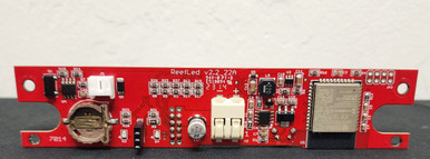
I'm very hopeful for this project - my wife's ReefLED 50 is ESP based, my AI Hydra 26HD's seem to be ESP based, and I know there's ESP based automatic feeders on Amazon that I'm tempted to toy with, as well as the wifi Jebao stuff.
If no one has seen anything like this, but there's interest in it on the forum, I'm also considering starting a YouTube channel to document my journey and throw some tutorials out there for the community (and probably get some sternly worded C&D letters from some manufacturers).
Has anyone explored reflashing off the shelf products with open source firmware such as Tasmota or Esphome? I've recently purchased a few of the newer M-series Jebao pumps/wavemakers. Cracked open the controller for my MDP-20000 and found an ESP8266 for wifi. I'm assuming the controllers for the two MLW-30's I just bought have the same or similar chips.
I'm working on re-tooling a dedicated Home Assistant server into what I'm dubbing "Reef Assistant". I've got a bunch of esp8266/esp32 boards monitoring and controlling basic functions, but am ready to start going a little deeper with this. Before I start bricking controllers, has anyone come across working instances of reflashed hardware? Pumps, wavemakers, automatic feeders, lights, etc etc.
I'm very hopeful for this project - my wife's ReefLED 50 is ESP based, my AI Hydra 26HD's seem to be ESP based, and I know there's ESP based automatic feeders on Amazon that I'm tempted to toy with, as well as the wifi Jebao stuff.
If no one has seen anything like this, but there's interest in it on the forum, I'm also considering starting a YouTube channel to document my journey and throw some tutorials out there for the community (and probably get some sternly worded C&D letters from some manufacturers).


")