Would a standalone solution require an analog computer? Reading the data sheets leads me to believe all computations are done at the sensor internally, generating a 4-20ma output which can be read by the ball valve directly.Having a stand alone is very compelling, but you’ll need to add some analog computer (mostly scaling) to get it to work. My personal take would be to build a stand alone controller for this out of any available microcontroller which is predictable and not subject to updates, power on lag, etc etc.
I don’t have experience with GHLs control system.
Navigation
Install the app
How to install the app on iOS
Follow along with the video below to see how to install our site as a web app on your home screen.
Note: This feature may not be available in some browsers.
More options
You are using an out of date browser. It may not display this or other websites correctly.
You should upgrade or use an alternative browser.
You should upgrade or use an alternative browser.
MaddyP's 12G Long - Node-Red Nano Peninsula
- Nano Build
- Thread starter MaddyP
- Start date
- Tagged users None
Would a standalone solution require an analog computer? Reading the data sheets leads me to believe all computations are done at the sensor internally, generating a 4-20ma output which can be read by the ball valve directly.
If you can set the range output to what you want in the small range, it would work just fine assuming both are 4-20mA loops (I thought the valve was 0-10V?)
The valve manufacturer offers a 4-20ma version of the smart actuator. And both the sensor and the valve are configurable by software. In theory, it shouldn't be too much trouble to calibrate these items together at a set water level and valve position.If you can set the range output to what you want in the small range, it would work just fine assuming both are 4-20mA loops (I thought the valve was 0-10V?)
As I move forward in planning out this tank, I keep running up against limitations with the available control systems available to our hobby (Apex / Profilux). I started a thread over on the GHL sub-forum to figure out if my idea would work through a Profilux, but the gurus couldn’t confirm or deny the control capabilities. And since the tank inhabitants will be entirely reliant of hardware keeping water in the display, I must minimize the risk of failure as much as possible.
@theatrus recommended building my own controller to facilitate this uniquely challenging application, which seems to me the best option. I’ve developed a few solutions for smaller tank with Arduino, but the development time and stability leads me to struggle with moving forward. Then it hit me! This is an automation project at its finest! Why not use a controller designed for automation?? It can interface everything I need: 4-20ma input/output, 0-10v input/output, inputs for switches/floats, and outputs for solenoids/relays/lights/pumps...the options are nearly endless. And, most PLC’s these days have a built in function for PID loop control, precisely the function I need to control the modulating valve and keep water at a consistent level.
Crazy? Overkill? Yes. But using a PLC will be much easier to program and offer a higher degree of confidence in operational stability. Not to mention, most systems are extremely versatile and modular. I don’t have much experience in using PLC’s, but it shouldn’t be too difficult. Certainly much less difficult than building a Arduino/Pi controller from scratch. Cost wise, several options are available with pricing comparable to a well equipped Apex/GHL setup.
AutomationDirect.com has several low cost PLC options targeted towards small projects. Click, Productivity Series, and Do-More BRX are a few options. Since I’m looking at this as an investment, I’ll likely go with the Productivity1000 or Productivity2000 so expansion down the line is available. These come with free software and a month of free training.


I’ve already ordered a modulating ball valve actuator and will handle water level sensing with a 40-300mm ultrasonic sensor from AutomationDirect.com. Most likely, I’ll also use these sensors for ATO reservoir and dosing reservoirs as they will provide my PLC with level which can be converted to volume with included software.


The P2000 PLC system has a built in OLED which can give status feedback about what’s happening with the system, but for ease of use one of these HMI’s will be added down the line.

More to come! Still deciding on dosing pump motors and ph/orp/conductivity probe integration. If anyone has experience in the PLC automation world, your input would be greatly appreciated!
@theatrus recommended building my own controller to facilitate this uniquely challenging application, which seems to me the best option. I’ve developed a few solutions for smaller tank with Arduino, but the development time and stability leads me to struggle with moving forward. Then it hit me! This is an automation project at its finest! Why not use a controller designed for automation?? It can interface everything I need: 4-20ma input/output, 0-10v input/output, inputs for switches/floats, and outputs for solenoids/relays/lights/pumps...the options are nearly endless. And, most PLC’s these days have a built in function for PID loop control, precisely the function I need to control the modulating valve and keep water at a consistent level.
Crazy? Overkill? Yes. But using a PLC will be much easier to program and offer a higher degree of confidence in operational stability. Not to mention, most systems are extremely versatile and modular. I don’t have much experience in using PLC’s, but it shouldn’t be too difficult. Certainly much less difficult than building a Arduino/Pi controller from scratch. Cost wise, several options are available with pricing comparable to a well equipped Apex/GHL setup.
AutomationDirect.com has several low cost PLC options targeted towards small projects. Click, Productivity Series, and Do-More BRX are a few options. Since I’m looking at this as an investment, I’ll likely go with the Productivity1000 or Productivity2000 so expansion down the line is available. These come with free software and a month of free training.
I’ve already ordered a modulating ball valve actuator and will handle water level sensing with a 40-300mm ultrasonic sensor from AutomationDirect.com. Most likely, I’ll also use these sensors for ATO reservoir and dosing reservoirs as they will provide my PLC with level which can be converted to volume with included software.
The P2000 PLC system has a built in OLED which can give status feedback about what’s happening with the system, but for ease of use one of these HMI’s will be added down the line.
More to come! Still deciding on dosing pump motors and ph/orp/conductivity probe integration. If anyone has experience in the PLC automation world, your input would be greatly appreciated!
Last edited:
As I move forward in planning out this tank, I keep running up against limitations with the available control systems available to our hobby (Apex / Profilux). I started a thread over on the GHL sub-forum to figure out if my idea would work through a Profilux, but the gurus couldn’t confirm or deny the control capabilities. And since the tank inhabitants will be entirely reliant of hardware keeping water in the display, I must minimize the risk of failure as much as possible.
@theatrus recommended building my own controller to facilitate this uniquely challenging application, which seems to me the best option. I’ve developed a few solutions for smaller tank with Arduino, but the development time and stability leads me to struggle with moving forward. Then it hit me! This is an automation project at its finest! Why not use a controller designed for automation?? It can interface everything I need: 4-20ma input/output, 0-10v input/output, inputs for switches/floats, and outputs for solenoids/relays/lights/pumps...the options are nearly endless. And, most PLC’s these days have a built in function for PID loop control, precisely the function I need to control the modulating valve and keep water at a consistent level.
Crazy? Overkill? Yes. But using a PLC will be much easier to program and offer a higher degree of confidence in operational stability. Not to mention, most systems are extremely versatile and modular. I don’t have much experience in using PLC’s, but it shouldn’t be too difficult. Certainly much less difficult than building a Arduino/Pi controller from scratch. Cost wise, several options are available with pricing comparable to a well equipped Apex/GHL setup.
AutomationDirect.com has several low cost PLC options targeted towards small projects. Click, Productivity Series, and Do-More BRX are a few options. Since I’m looking at this as an investment, I’ll likely go with the Productivity1000 or Productivity2000 so expansion down the line is available. These come with free software and a month of free training.


I’ve already ordered a modulating ball valve actuator and will handle water level sensing with a 40-300mm ultrasonic sensor from AutomationDirect.com. Most likely, I’ll also use these sensors for ATO reservoir and dosing reservoirs as they will provide my PLC with level which can be converted to volume with included software.


The P2000 PLC system has a built in OLED which can give status feedback about what’s happening with the system, but for ease of use one of these HMI’s will be added down the line.

More to come! Still deciding on dosing pump motors and ph/orp/conductivity probe integration. If anyone has experience in the PLC automation world, your input would be greatly appreciated!
PLC is a great application especially if you already have the industrial standard 0-10 and 4-20 sensors and actuators. Some of the PLC programming environments can be quite esoteric but I’ve dealt with AutomationDirect equipment before and it’s a solid value.
This is my first excursion into PLC’s, thank you for the encouragement!PLC is a great application especially if you already have the industrial standard 0-10 and 4-20 sensors and actuators. Some of the PLC programming environments can be quite esoteric but I’ve dealt with AutomationDirect equipment before and it’s a solid value.
As I continue to expand on this idea of drains and returns in the bottom of the tank and the desire to utilize a standard sump, I kept running into the same problem of how to keep the display from draining entirely into the sump. Even if this were solved, an additional problem would be how to balance the water in and water out of the display? Then it came to me. Why not use a high flow float valve to balance the flow? We rely on float valves in other areas of our aquarium set ups, why not here? It wouldn't need to be bullet proof, just help cut off the flow if too much water came down from the display and allow more if the pump is pushing too much water. I've developed a proof of concept to see if this will even work. Should have the components in a couple days!
How it should work in theory: water flows at full siphon down from display which causes water level to fluctuate in sump. As water fluctuates, the float valve will close accordingly. I'm thinking the float and pump will find an equilibrium. I can then "calibrate" the water level in the display by removing or adding water to the system.
Thoughts?


What if you ran the drains out the bottom, elbowed to the back of the tank, elbowed up to where you wanted the water line (use a tee here to go higher as a siphon break) then drop back down in the the sump. It meets your goal of no visible plumbing in the tank, but you could only get water drained if the water in the tank was high enough(from the return pump). It would effectively act like a normal overflow does.
Problem I see with your large flow float valve, is that mechanical piece that connects the float and mechanism to close/open the valve is going to get a lot of salt creep and likely fail overtime. Then you’ll siphon the whole tank dry and overflow the sump.
This was another idea I considered, but with the space I have the plumbing would be visible behind the tank which defeats the purpose of this setup.What if you ran the drains out the bottom, elbowed to the back of the tank, elbowed up to where you wanted the water line (use a tee here to go higher as a siphon break) then drop back down in the the sump. It meets your goal of no visible plumbing in the tank, but you could only get water drained if the water in the tank was high enough(from the return pump). It would effectively act like a normal overflow does.
Problem I see with your large flow float valve, is that mechanical piece that connects the float and mechanism to close/open the valve is going to get a lot of salt creep and likely fail overtime. Then you’ll siphon the whole tank dry and overflow the sump.
The float valve was a long shot anyway and didn’t actually control water level in a consistent manner. Utilizing a modulating ball valve should work great though. I’ve seen several other applications in industrial setting doing something similar to my goals here.
The last week has involved a massive amount of research to decide which components to go with on this build. I'm glad to write, most of the control components have been ordered! Below will cover a brief overview of the components.
Control
Productivity 1000 PLC
(1) CPU
(1) Discrete Input Module (16-point)
(1) Discrete Output Module (16 points)
(1) Analog Current Combo Module (4-point Input, 2-point Output)
(2) Analog Voltage Output Module (4-point)
Raspberry PI
(1) Raspberry Pi 3B+
(1) DIN Rail Mount for Pi
Power - 5VDC and 24VDC
(1) Rhino Power Supply (24VDC 10A)
(1) Rhino Power Supply (5VDC 3A)
Interface Devices
Ultrasonic Sensor (40-300mm, 4-20ma Output)
AVA Electric Actuator (4-20ma Input)
The addition of Raspberry Pi to this build will be to facilitate a web page for monitoring and controlling the PLC. Before, the idea was to use a C-More Micro HMI but this seemed rather limiting especially with remote access to the controller. I also don't want to see a small screen with large bevel obscuring the beauty of the setup. Somehow while looking for an alternative to a classic HMI panel, the ability to utilize a IOT development platform (Node Red) came to the surface. I was even able to find a tutorial on how to establish a communication from the Raspberry Pi to a PLC via Modbus TCP.
Once complete, the dashboard should look something like a combination of these...


Most of the components should arrive later this week. Hopefully, I can start working on the PLC and Raspberry Pi communication this weekend to verify everything works as expected. Then, designing the electrical side of the stand to verify everything fits properly.
Control
Productivity 1000 PLC
(1) CPU
(1) Discrete Input Module (16-point)
(1) Discrete Output Module (16 points)
(1) Analog Current Combo Module (4-point Input, 2-point Output)
(2) Analog Voltage Output Module (4-point)
Raspberry PI
(1) Raspberry Pi 3B+
(1) DIN Rail Mount for Pi
Power - 5VDC and 24VDC
(1) Rhino Power Supply (24VDC 10A)
(1) Rhino Power Supply (5VDC 3A)
Interface Devices
Ultrasonic Sensor (40-300mm, 4-20ma Output)
AVA Electric Actuator (4-20ma Input)
The addition of Raspberry Pi to this build will be to facilitate a web page for monitoring and controlling the PLC. Before, the idea was to use a C-More Micro HMI but this seemed rather limiting especially with remote access to the controller. I also don't want to see a small screen with large bevel obscuring the beauty of the setup. Somehow while looking for an alternative to a classic HMI panel, the ability to utilize a IOT development platform (Node Red) came to the surface. I was even able to find a tutorial on how to establish a communication from the Raspberry Pi to a PLC via Modbus TCP.
Once complete, the dashboard should look something like a combination of these...
Most of the components should arrive later this week. Hopefully, I can start working on the PLC and Raspberry Pi communication this weekend to verify everything works as expected. Then, designing the electrical side of the stand to verify everything fits properly.
Last edited:
Another part of the build will be further developing the control and monitoring features.
Probes
One way to expand on this control system to monitor pH, ORP, conductivity, dissolved oxygen, CO2, and temp is to use a RaspPi shield developed by Atlas Scientific. The Tentacle T3 can be stacked two high allowing for four isolated sensors, two temp sensors, and four 5-pin sensors (flow, pressure, CO2). This shield communicates through I2C so shouldn't get in the way of PLC communications. It is also configurable so if I choose to utilize different probes, it's a simple chip swap. Though I've never used these before, accuracy is adequate for saltwater purposes.
But more importantly, Node Red has flows and nodes to incorporate I2C communication right into the dashboard.
Whitebox Labs Tentacle T3

Power Control
As for controlling different 110v equipment in the sump, the plan as of now is to take a power strip with adequate room between outlets and install 24V coil relays for outlet to outlet control. I haven't yet decided if I want the relays to exist in the electrical cabinet or in the power strip itself. If relays are placed in the cabinet, then only one cord can be ran to the power strip. Though, it would need to be adequate to handle the current draw of any connected equipment. Were the relays to be in the power strip, two cords would have to be utilized: one for power, the other for relay communication. Another thought is to build outlets into the back side of the equipment cabinet itself, removing the need for a separate power module. Equipment would then just be ran to the side of the cabinet and plug in somewhere up top.
Probes
One way to expand on this control system to monitor pH, ORP, conductivity, dissolved oxygen, CO2, and temp is to use a RaspPi shield developed by Atlas Scientific. The Tentacle T3 can be stacked two high allowing for four isolated sensors, two temp sensors, and four 5-pin sensors (flow, pressure, CO2). This shield communicates through I2C so shouldn't get in the way of PLC communications. It is also configurable so if I choose to utilize different probes, it's a simple chip swap. Though I've never used these before, accuracy is adequate for saltwater purposes.
But more importantly, Node Red has flows and nodes to incorporate I2C communication right into the dashboard.
Whitebox Labs Tentacle T3
Power Control
As for controlling different 110v equipment in the sump, the plan as of now is to take a power strip with adequate room between outlets and install 24V coil relays for outlet to outlet control. I haven't yet decided if I want the relays to exist in the electrical cabinet or in the power strip itself. If relays are placed in the cabinet, then only one cord can be ran to the power strip. Though, it would need to be adequate to handle the current draw of any connected equipment. Were the relays to be in the power strip, two cords would have to be utilized: one for power, the other for relay communication. Another thought is to build outlets into the back side of the equipment cabinet itself, removing the need for a separate power module. Equipment would then just be ran to the side of the cabinet and plug in somewhere up top.
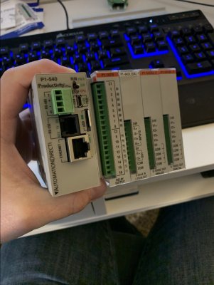
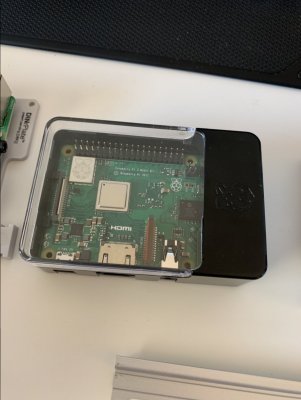
Raspiberry Pi and PLC arrived yesterday! So excited to play around with this stuff! Everything will be DIN mounted for ease, even found a mount for the Pi.
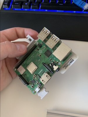
Bought an additional Pi for development purposes. I’ll use it to verify everything works before flashing the new configuration to the PLC-Pi.
And everything hooked up For communication.
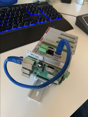
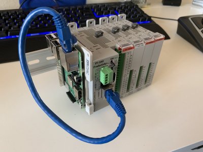
Once everything is in place on a test panel, I'll reconfigure wiring so the ethernet cable isn't so obnoxious.


Bought an additional Pi for development purposes. I’ll use it to verify everything works before flashing the new configuration to the PLC-Pi.

And everything hooked up For communication.


Once everything is in place on a test panel, I'll reconfigure wiring so the ethernet cable isn't so obnoxious.
After flashing Raspbian to a microSD, installing Node-Red was easy.
Enables ssh by creating a ssh.txt (empty file) in the /boot/ of Raspbian and using Putty to connect over Ethernet to the Pi. Once wifi is configured properly, the Ethernet will be connected to the PLC for Modbus TCP communications.
Then install a couple of useful nodes:
And enable Node-Red to run when Pi boots up:
Reboot Pi and Node-Red should be up and running at http://(Pi IP Address:1880)/#/

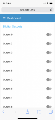
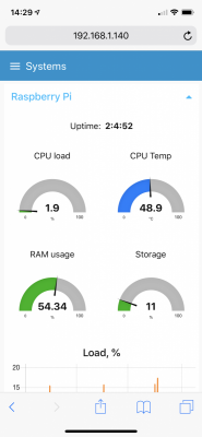
As you can see, I put together a simple test to verify it works as intended. This quick flow uses a "ping" to ping Google.com every second and return the result to a gauge. Once deployed, the dashboard is available at http://(Pi IP Address:1880)/ui/

And a quick change to chart...

Enables ssh by creating a ssh.txt (empty file) in the /boot/ of Raspbian and using Putty to connect over Ethernet to the Pi. Once wifi is configured properly, the Ethernet will be connected to the PLC for Modbus TCP communications.
Code:
bash <(curl -sL https://raw.githubusercontent.com/node-red/raspbian-deb-package/master/resources/update-nodejs-and-nodered)Then install a couple of useful nodes:
Code:
cd ~/.node-red
Code:
npm install node-red-contrib-modbus
Code:
npm install node-red-dashboard
Code:
npm install node-red-contrib-i2cAnd enable Node-Red to run when Pi boots up:
Code:
sudo systemctl enable nodered.serviceReboot Pi and Node-Red should be up and running at http://(Pi IP Address:1880)/#/
As you can see, I put together a simple test to verify it works as intended. This quick flow uses a "ping" to ping Google.com every second and return the result to a gauge. Once deployed, the dashboard is available at http://(Pi IP Address:1880)/ui/
And a quick change to chart...
Last edited:
Another part of the build will be further developing the control and monitoring features.
Probes
One way to expand on this control system to monitor pH, ORP, conductivity, dissolved oxygen, CO2, and temp is to use a RaspPi shield developed by Atlas Scientific. The Tentacle T3 can be stacked two high allowing for four isolated sensors, two temp sensors, and four 5-pin sensors (flow, pressure, CO2). This shield communicates through I2C so shouldn't get in the way of PLC communications. It is also configurable so if I choose to utilize different probes, it's a simple chip swap. Though I've never used these before, accuracy is adequate for saltwater purposes.
But more importantly, Node Red has flows and nodes to incorporate I2C communication right into the dashboard.
Whitebox Labs Tentacle T3

Ordered this Tentacle T3 shield along with pH and ORP boards. This should work well with the Pi and Node-Red-I2C to integrate seamlessly into my dashboard. Even though the PLC isn't directly reading the probe values, if something is off too much I can trigger the PLC with a modbus write command. Integrating the probes directly into the PLC was more effort than it was worth and will primarily be used for monitoring only.
Temp will be integrated directly to the PLC so a PID loop can be used for control. This isn't necessary, but I'm curious as to how stable I can get the temp. I might use the temp part of the Tentacle shield to monitor controller or lighting temperatures.
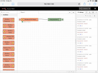
Made some progress playing around with Node-Red. Also established communication (ModbusTCP) with the PLC.


Next step will be to develop electrical area of the tank stand: build power strip module, dosing module, and sensor module. Once these modules are built it will be much easier to figure out placement in the stand. Then wiring and organizing!
Next step will be to develop electrical area of the tank stand: build power strip module, dosing module, and sensor module. Once these modules are built it will be much easier to figure out placement in the stand. Then wiring and organizing!
Made some progress with the controller. Decided to go with the Tentacle shield for PH/ORP/Cond/DO monitoring by stacking two shields. Stacking will also give me (4) ports to use with peristaltic pumps. The pumps offered by Atlas Scientific seem to be decent quality and have numerous functions built into the board. So far, I only have one board for development, but another is on the way with a peristaltic pump for testing.
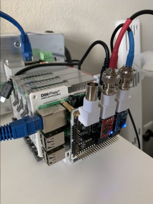
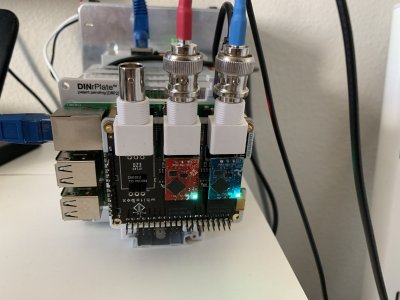
The datasheets for these EZO boards show a maximum polling rate of 1.5 seconds, but 1 second works find once the code is tweaked. Getting the EZO boards to work properly in Node-Red took some doing, I'm happy to share my code if anyone is interested.

On another note, the critical part of this system arrived also. Since this was ordered from Ebay, I wasn't quite sure what would arrive. This actuator seems to be every bit the quality of a AVA actuator at a fraction of the cost. To be extra sure, I took this apart to see if the internals matched the quality of the externals. Should be interesting getting this implemented in my concept tanks. Don't yet have the ball valve, should have it next week as it was ordered through a UK distributor.
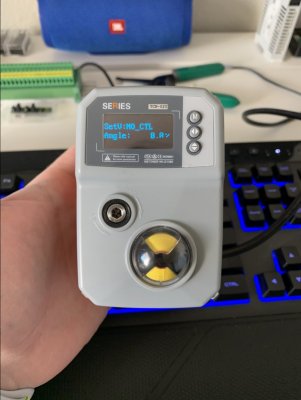
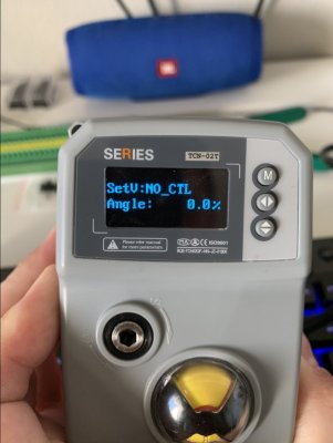
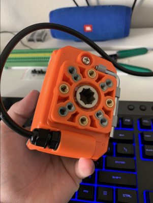


The datasheets for these EZO boards show a maximum polling rate of 1.5 seconds, but 1 second works find once the code is tweaked. Getting the EZO boards to work properly in Node-Red took some doing, I'm happy to share my code if anyone is interested.
On another note, the critical part of this system arrived also. Since this was ordered from Ebay, I wasn't quite sure what would arrive. This actuator seems to be every bit the quality of a AVA actuator at a fraction of the cost. To be extra sure, I took this apart to see if the internals matched the quality of the externals. Should be interesting getting this implemented in my concept tanks. Don't yet have the ball valve, should have it next week as it was ordered through a UK distributor.


Last edited:
Ya know, from a technical standpoint I have absolutely no idea what I’m reading in this thread but I like it. The idea of being able to come up with the concept and then build a controller to make it work is really cool. I hope it all works perfectly when you are done.
Thanks! We'll see if it actually works though...Ya know, from a technical standpoint I have absolutely no idea what I’m reading in this thread but I like it. The idea of being able to come up with the concept and then build a controller to make it work is really cool. I hope it all works perfectly when you are done.
Similar threads
- Replies
- 25
- Views
- 398
- Replies
- 8
- Views
- 505


