MaddyP's 12G Long - Node-Red Nano Peninsula

MaddyP

'Til Reefdom Come...
View Badges
Joined
Jul 21, 2016
Messages
1,907
Reaction score
4,530
Location
Vancouver, WA
Rating - 0%
0   0   0
Fellow Reefers, lend me your minds!

I have decided to embark on a rather unconventional mission, though I have some doubts as to how successful such a system will be. As such, I thought it wise to consult the community for additional ideas.

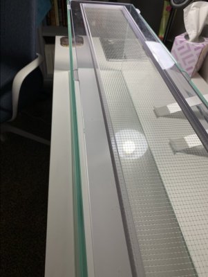
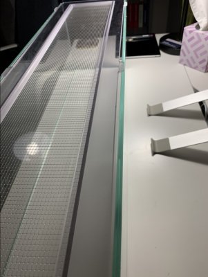
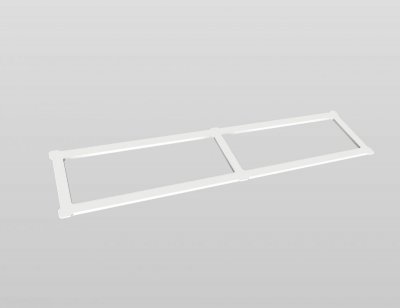
The primary goal for this build is to create a nano reef system without any visible plumbing in the display. Placing plumbing in the bottom of the tank isn't a new idea, but creating a system with a fully closed loop which includes a refugium/frag tank hasn't been done as far as my research shows. If anyone can find research on a similar build, I would love to see it. I would then epoxy rock rubble around the plumbing. Both 45 returns will be heated and flattened to spread out the flow to the width of the tank as well as being disguised with rock rubble. Overall, I think the display portion of the build to be the most straight forward and should look nice when complete.

upload_2019-2-1_15-22-17.png


upload_2019-2-1_15-29-1.png


upload_2019-2-1_15-28-30.png


As for the rest of the system, I started with a simple "plumbing only" design with ports for reactors (media, algae, additional volume, calcium reactor). This design seems the most reasonable as it mimics a closed loop system commonly used in large aquaria and it would allow maximum flexibility for components. I also chose to utilize two pumps so I could vary the flow from one side of the tank to the other.

upload_2019-2-1_15-19-38.png


And with the potential equipment and reservoirs. From left to right (top to bottom): Custom Nanobox Fixture (ships on Monday), GHL system, ATO and dosing reservoirs, 2.5lbs CO2 tank, aquamaxx reactor, aquamaxx nano calcium reactor, Pax Bellum N18 algae reactor, and dual chamber auto water change reservoir.

upload_2019-2-1_15-30-35.png


After a lot of thought and messing around, I decided to do something a little different and eliminate as much plumbing as possible. Same design for the display, but a little different below.

upload_2019-2-1_15-41-30.png


This design utilizes a sealed sump design to keep with the closed loop and reduces the number of connections substantially, reducing the risk of a leak. Yes, it's a little unorthodox, but I don't see any reason this won't work. I haven't added the additional equipment yet as I wanted as much input before putting all that work into the design.

I'm open to suggestions/ideas!


OP
OP
MaddyP

MaddyP

'Til Reefdom Come...
View Badges
Joined
Jul 21, 2016
Messages
1,907
Reaction score
4,530
Location
Vancouver, WA
Rating - 0%
0   0   0

theatrus

Valuable Member
View Badges
Joined
Mar 26, 2016
Messages
1,950
Reaction score
3,351
Location
Sacramento, CA area
Rating - 0%
0   0   0
How are you planning to maintain the pressurized sump? Or am I misunderstanding that portion?

Very interested in the design here. I’m doing a more conventional setup for my 22glong but love seeing all the ideas floating about.
 
OP
OP
MaddyP

MaddyP

'Til Reefdom Come...
View Badges
Joined
Jul 21, 2016
Messages
1,907
Reaction score
4,530
Location
Vancouver, WA
Rating - 0%
0   0   0
How are you planning to maintain the pressurized sump? Or am I misunderstanding that portion?

Very interested in the design here. I’m doing a more conventional setup for my 22glong but love seeing all the ideas floating about.
I'm not sure if it could be considered pressurized, though it will be sealed. There will be a ring of thumb screws around the lid of the sump to seal it, I haven't gotten around to finish those fine details. And the plumbing going into the sump will be uniseals.
 

theatrus

Valuable Member
View Badges
Joined
Mar 26, 2016
Messages
1,950
Reaction score
3,351
Location
Sacramento, CA area
Rating - 0%
0   0   0
I'm not sure if it could be considered pressurized, though it will be sealed. There will be a ring of thumb screws around the lid of the sump to seal it, I haven't gotten around to finish those fine details. And the plumbing going into the sump will be uniseals.

Won’t you have effectively the head height of water from the tank in the sump? It’s not intentionally pressurized but will need a good seal for any openings.
 
OP
OP
MaddyP

MaddyP

'Til Reefdom Come...
View Badges
Joined
Jul 21, 2016
Messages
1,907
Reaction score
4,530
Location
Vancouver, WA
Rating - 0%
0   0   0
Won’t you have effectively the head height of water from the tank in the sump? It’s not intentionally pressurized but will need a good seal for any openings.
Maybe, but at the same time water moves down the drains and into the sump, pumps will be pulling water out of the sump and sending it back up to the tank. In theory, this should negate any pressure. If anything I don’t believe the sump will see more than a few PSI of pressure.
 

theatrus

Valuable Member
View Badges
Joined
Mar 26, 2016
Messages
1,950
Reaction score
3,351
Location
Sacramento, CA area
Rating - 0%
0   0   0
Maybe, but at the same time water moves down the drains and into the sump, pumps will be pulling water out of the sump and sending it back up to the tank. In theory, this should negate any pressure. If anything I don’t believe the sump will see more than a few PSI of pressure.

3 feet of water is 1.3PSI, not a lot but not trivial to stay leak free. Excited for this build :)
 

eschulist

Active Member
View Badges
Joined
Apr 4, 2012
Messages
352
Reaction score
802
Location
Minneapolis
Rating - 0%
0   0   0
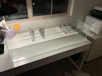
Credit for the tank and lighting choice goes to @eschulist and his 3 Foot Office build. Thank you for giving us a great example of how a well designed and maintained nano can become. If you haven't seen his build thread, it's amazing...

https://www.reef2reef.com/threads/3-foot-office-nano.226049/

Thanks for the shout out!! Glad you like it.

Your first tank concept with every filtration component being plumbed together and having 4 inline probe holders is really high concept. I think the thing you are fighting is having both drains and both returns being plumbed together. Is there any harm in having a large 1.5-2" drain in the center of the tank covered by a large hallowed out rock. Drop that down and to the left. Then in a straight line go through 2-3 canister filters. One carbon / GFO / Clear LED wrapped Cheato / biopellets etc. Then an inline heater and push it all back into the tank with a single pump that splits its returns as two 3/4" Were you going to do a recirculating calcium reactor with a solenoid valve to inject effluent into the line? You'd probably have to do a similar solenoid to inject freshwater into the line. The challenge is you have nothing to gauge water level as your tank water will fluctuate rather inside the usual sump. You could always sttach an optical sensor near the rim of the tank, but if youre like me you dont want a single cord anywhere near the glass.
 
OP
OP
MaddyP

MaddyP

'Til Reefdom Come...
View Badges
Joined
Jul 21, 2016
Messages
1,907
Reaction score
4,530
Location
Vancouver, WA
Rating - 0%
0   0   0
Thanks for the shout out!! Glad you like it.

Your first tank concept with every filtration component being plumbed together and having 4 inline probe holders is really high concept. I think the thing you are fighting is having both drains and both returns being plumbed together. Is there any harm in having a large 1.5-2" drain in the center of the tank covered by a large hallowed out rock. Drop that down and to the left. Then in a straight line go through 2-3 canister filters. One carbon / GFO / Clear LED wrapped Cheato / biopellets etc. Then an inline heater and push it all back into the tank with a single pump that splits its returns as two 3/4" Were you going to do a recirculating calcium reactor with a solenoid valve to inject effluent into the line? You'd probably have to do a similar solenoid to inject freshwater into the line. The challenge is you have nothing to gauge water level as your tank water will fluctuate rather inside the usual sump. You could always sttach an optical sensor near the rim of the tank, but if youre like me you dont want a single cord anywhere near the glass.

Something like this?

upload_2019-2-2_13-37-56.png


upload_2019-2-2_13-38-21.png


upload_2019-2-2_13-38-46.png
 
OP
OP
MaddyP

MaddyP

'Til Reefdom Come...
View Badges
Joined
Jul 21, 2016
Messages
1,907
Reaction score
4,530
Location
Vancouver, WA
Rating - 0%
0   0   0
Thanks for the shout out!! Glad you like it.

Your first tank concept with every filtration component being plumbed together and having 4 inline probe holders is really high concept. I think the thing you are fighting is having both drains and both returns being plumbed together. Is there any harm in having a large 1.5-2" drain in the center of the tank covered by a large hallowed out rock. Drop that down and to the left. Then in a straight line go through 2-3 canister filters. One carbon / GFO / Clear LED wrapped Cheato / biopellets etc. Then an inline heater and push it all back into the tank with a single pump that splits its returns as two 3/4" Were you going to do a recirculating calcium reactor with a solenoid valve to inject effluent into the line? You'd probably have to do a similar solenoid to inject freshwater into the line. The challenge is you have nothing to gauge water level as your tank water will fluctuate rather inside the usual sump. You could always sttach an optical sensor near the rim of the tank, but if youre like me you dont want a single cord anywhere near the glass.

I want to use dual pumps so I can vary the flow from one end of the tank to the other. Similar to your design with cross flow, but controllable. Originally, I chose two drains so the intake pressure wouldn't bee too much for the smaller inhabitants of the tank. The reason I chose long strainers is because I wanted to leave space between the rock work allowing flow under and between the branches of corals. Not sure if this will help, but the idea seems reasonable in a small tank.

And yes, I haven't decided which sensor I will use but there will need to be a level sensor at the display for evaporation control. I'll use check valves for the dosing and ato lines, both will be fed with peristaltic pumps anyway. Probably won't go with a calcium reactor, on such a small tank dosing will be economical enough.
 
OP
OP
MaddyP

MaddyP

'Til Reefdom Come...
View Badges
Joined
Jul 21, 2016
Messages
1,907
Reaction score
4,530
Location
Vancouver, WA
Rating - 0%
0   0   0
As I continue to expand on this idea of drains and returns in the bottom of the tank and the desire to utilize a standard sump, I kept running into the same problem of how to keep the display from draining entirely into the sump. Even if this were solved, an additional problem would be how to balance the water in and water out of the display? Then it came to me. Why not use a high flow float valve to balance the flow? We rely on float valves in other areas of our aquarium set ups, why not here? It wouldn't need to be bullet proof, just help cut off the flow if too much water came down from the display and allow more if the pump is pushing too much water. I've developed a proof of concept to see if this will even work. Should have the components in a couple days!

How it should work in theory: water flows at full siphon down from display which causes water level to fluctuate in sump. As water fluctuates, the float valve will close accordingly. I'm thinking the float and pump will find an equilibrium. I can then "calibrate" the water level in the display by removing or adding water to the system.

Thoughts?

upload_2019-2-5_14-9-7.png
upload_2019-2-5_14-9-42.png
 

theatrus

Valuable Member
View Badges
Joined
Mar 26, 2016
Messages
1,950
Reaction score
3,351
Location
Sacramento, CA area
Rating - 0%
0   0   0
As I continue to expand on this idea of drains and returns in the bottom of the tank and the desire to utilize a standard sump, I kept running into the same problem of how to keep the display from draining entirely into the sump. Even if this were solved, an additional problem would be how to balance the water in and water out of the display? Then it came to me. Why not use a high flow float valve to balance the flow? We rely on float valves in other areas of our aquarium set ups, why not here? It wouldn't need to be bullet proof, just help cut off the flow if too much water came down from the display and allow more if the pump is pushing too much water. I've developed a proof of concept to see if this will even work. Should have the components in a couple days!

How it should work in theory: water flows at full siphon down from display which causes water level to fluctuate in sump. As water fluctuates, the float valve will close accordingly. I'm thinking the float and pump will find an equilibrium. I can then "calibrate" the water level in the display by removing or adding water to the system.

Thoughts?

upload_2019-2-5_14-9-7.png
upload_2019-2-5_14-9-42.png

Totally worth testing with a pair of cheapy tanks. You also might end up with a system that oscillates, which may be interesting.

You'll need to monitor the display water level since evap will still effect it most (the sump will remain at a constant level). Using a piece of clear rigid airline and a pressure sensor would be a good way to monitor levels.
 

chefjpaul

2500 Club Member
View Badges
Joined
May 21, 2014
Messages
3,278
Reaction score
4,667
Location
South Florida
Rating - 0%
0   0   0
Made a little more progress with the plumbing per @eschulist single drain idea.

upload_2019-2-3_23-10-10.png
I love the concept. I personally would run just one pump to both returns and adjust flow with the valves, I understand your idea behind 2 pumps, but it could be a setup for failure unless your sump will maintain the whole display waters displacement.
 
OP
OP
MaddyP

MaddyP

'Til Reefdom Come...
View Badges
Joined
Jul 21, 2016
Messages
1,907
Reaction score
4,530
Location
Vancouver, WA
Rating - 0%
0   0   0
Totally worth testing with a pair of cheapy tanks. You also might end up with a system that oscillates, which may be interesting.

You'll need to monitor the display water level since evap will still effect it most (the sump will remain at a constant level). Using a piece of clear rigid airline and a pressure sensor would be a good way to monitor levels.
Yes, I'm expecting to need some kind of sensor in the display for evap, the clear tubing is a great idea! I was planning to use an Avast Marine pressure switch anyway!
 
OP
OP
MaddyP

MaddyP

'Til Reefdom Come...
View Badges
Joined
Jul 21, 2016
Messages
1,907
Reaction score
4,530
Location
Vancouver, WA
Rating - 0%
0   0   0
I love the concept. I personally would run just one pump to both returns and adjust flow with the valves, I understand your idea behind 2 pumps, but it could be a setup for failure unless your sump will maintain the whole display waters displacement.
The idea behind two pumps is to use 0-10V to vary the flow from side to side, eliminating any power heads. This way I'll still get varying flow but won't tarnish the 360 view of the tank.
 

Fusion in reefing: How do you feel about grafted corals?

  • I strongly prefer grafted corals and I seek them out to put in my tank.

    Votes: 3 3.3%
  • I find grafted corals appealing and would be open to having them in my tank.

    Votes: 51 56.0%
  • I am indifferent about grafted corals and am not enthusiastic about having them in my tank.

    Votes: 27 29.7%
  • I have reservations about grafted corals and would generally avoid having them in my tank.

    Votes: 7 7.7%
  • I have a negative perception and would avoid having grafted corals in my tank.

    Votes: 3 3.3%
Back
Top