This thread should be pinned in my opinion  . its such a popular thing, making these blackboxes dimmable is a big deal, it will help a lot of users
Navigation
Install the app
How to install the app on iOS
Follow along with the video below to see how to install our site as a web app on your home screen.
Note: This feature may not be available in some browsers.
More options
You are using an out of date browser. It may not display this or other websites correctly.
You should upgrade or use an alternative browser.
You should upgrade or use an alternative browser.
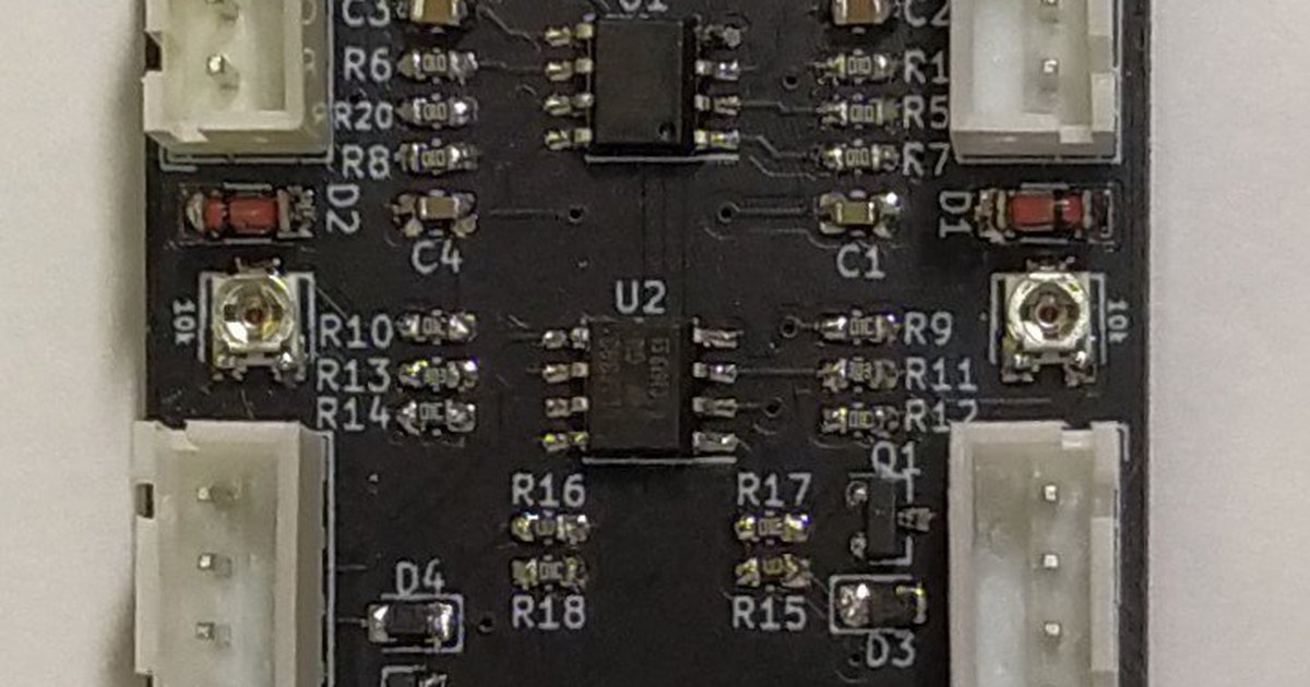
Mars Aqua Chinese black box PWM Converter
- Thread starter Michael Lane
- Start date
- Tagged users None
Hey @Michael Lane , working on adding light dimming to my Mars Aqua & came across this. I'm a bit unclear on how this ties into a reef-pi setup. Is this in place of the diagram on adafruit? In addition to? How does it connect to the pi/lights? Would I need one per light? I couldn't really find much of a write-up anywhere on these, so thought you may be able to shine some light 
- Joined
- Jul 1, 2019
- Messages
- 688
- Reaction score
- 924
@Michael Lane @Schreiber I too am looking at how to connect/modify my SB Reef Basic lights.
I will be purchasing the Goby and PWM this Friday (Payday) from Tindie.
Here is the inside of my SB Basic (mind the dust)

 for help on above.
I will be purchasing the Goby and PWM this Friday (Payday) from Tindie.
Here is the inside of my SB Basic (mind the dust)
- Joined
- Aug 11, 2018
- Messages
- 677
- Reaction score
- 1,123
@Schreiber The PWM adapters were designed before I had even heard of reef-pi, but they work great together. My design uses one board per light; the 4 pin connector from each original knob is plugged into the board. 2 pwm channels and ground plug into one of the 3 pin connectors. The other 3 pin connector can be used to daisy chain the signal to the next light.

I have 8 connected on my system. I can't get a clear picture of them in the canopies, but it's basically like this.

I'm using the normal lights functionality in reef-pi using PCA9685 for PWM generation.

I have 8 connected on my system. I can't get a clear picture of them in the canopies, but it's basically like this.
I'm using the normal lights functionality in reef-pi using PCA9685 for PWM generation.
- Joined
- Aug 11, 2018
- Messages
- 677
- Reaction score
- 1,123
@Urtoo I don't know how the SB Reef Basic lights are controlled, and I haven't tested them with my Mars Aqua adapter. I can see how the light is powered, but I can't see how they can be adjusted. The adapter I've made converts pwm to 0-10v analog and acts as a switch under a threshold voltage. We'd need to know more about the SB lights.
- Joined
- Jul 1, 2019
- Messages
- 688
- Reaction score
- 924
I will gladly remove them and get the connectors off to see them. Also search my drivers pin outs to the switches themselves
I need to do this to replace the fans as o e is making a noise now, probably order noctura ....Tomorrow
I need to do this to replace the fans as o e is making a noise now, probably order noctura ....Tomorrow
- Joined
- Aug 11, 2018
- Messages
- 677
- Reaction score
- 1,123
Looks pretty close,with some assumptions. The adapter board needs 12v applied to V+.
I am going to assume to match:
From SB Reef | ML PWM Board
Ground ground
on/off pm/off
0-10v vdim
(null) V+
Is this correct?
Are there any other wires coming in to that board? I don't see how it is able to generate 0-10v without a voltage source (unless ON/OFF is actually 12v). Could you measure voltage on the ON/OFF pin in a few different settings (off, 30%, 60%, 100% for example).
We'll just need to confirm the ON/OFF pin and identify where 12v might be available.
- Joined
- Sep 18, 2017
- Messages
- 5,585
- Reaction score
- 3,439
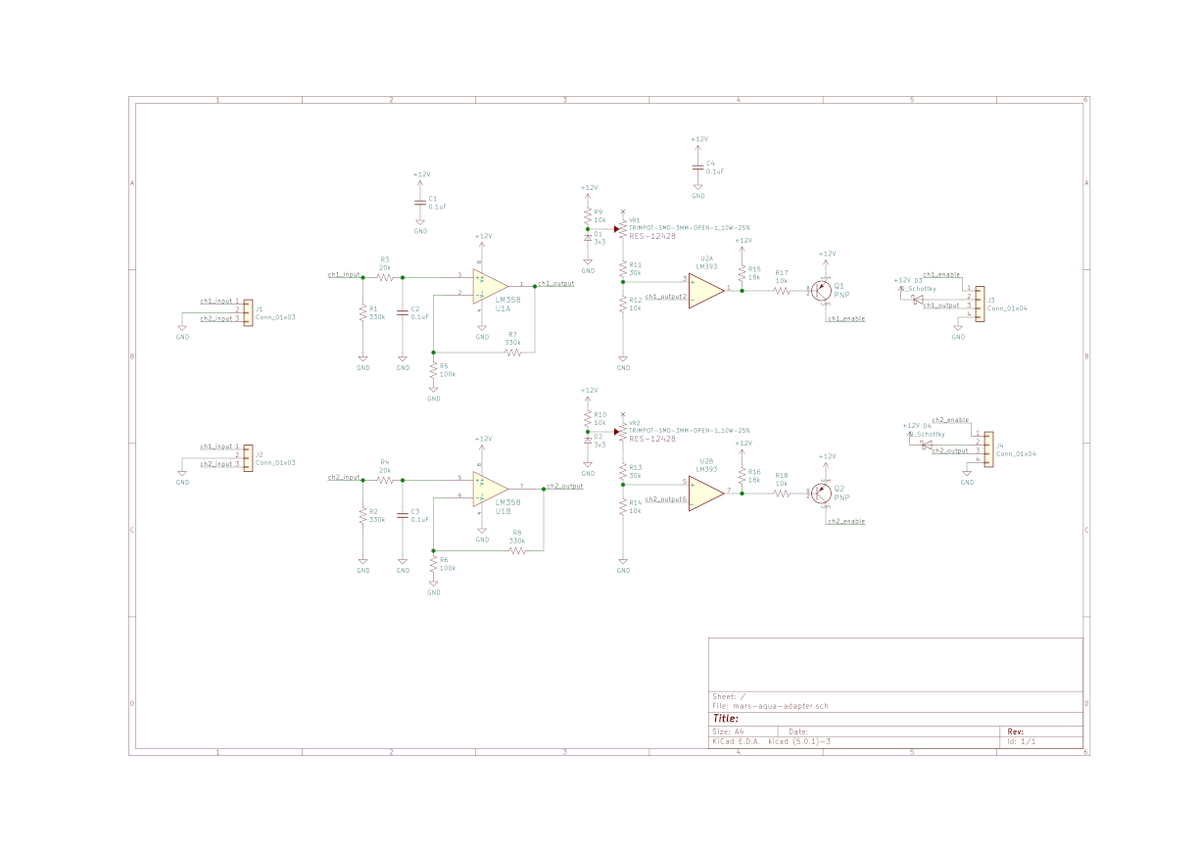
Schematic..Looks pretty close,with some assumptions. The adapter board needs 12v applied to V+.
Are there any other wires coming in to that board? I don't see how it is able to generate 0-10v without a voltage source (unless ON/OFF is actually 12v). Could you measure voltage on the ON/OFF pin in a few different settings (off, 30%, 60%, 100% for example).
We'll just need to confirm the ON/OFF pin and identify where 12v might be available.

PWM Converter for Mars Aqua by ML Reefkeeping on Tindie
Control Mars Aqua LED lights with PWM

I feel late to this party. I have a blackbox and want to control it with my Profilux 2...it is my understanding it will dim/control the lights with this? The profilux does 0-10v unless we convert it into pwm. Not sure how the Reefpi controls the bb lights. This board looks great! Just wanted to see what everyone thinks here. If easier to swap out the drivers I can also do that as I have some ldd-h and Eln drivers laying around. Thanks in advance!
- Joined
- Aug 11, 2018
- Messages
- 677
- Reaction score
- 1,123
reef-pi typically uses PWM to control lights, which was part of my motivation for this board. If you already have 0-10v output from the profilux, then this circuit would not work for you since it boosts the voltage.I feel late to this party. I have a blackbox and want to control it with my Profilux 2...it is my understanding it will dim/control the lights with this? The profilux does 0-10v unless we convert it into pwm. Not sure how the Reefpi controls the bb lights. This board looks great! Just wanted to see what everyone thinks here. If easier to swap out the drivers I can also do that as I have some ldd-h and Eln drivers laying around. Thanks in advance!
I've made a couple of changes to this design since the schematic above was posted. I've replaced the zener and potentiometer with a TL431. If you are interested, I could post an updated schematic and board layout.
It could probably be modified to work with 0-10v input with the following modifications.
- replace R7 and R8 with a 0 ohm resistor
- Leave R5 and R6 unpopulated
This would buffer the signal from the profilux (probably doesn't add much value), and automatically turn the lights off when it drops below the threshold. I'm not 100% sure it would work with profilux since I haven't tried it. It's also possible that the analog output doesn't actually drop to 0v, so it would be interesting to test it.
I'm coming into the party late as well.
I have a sbreeflights 32" basic that I have made a custom PCB to dim. The circuit is also plug and play, just disconnect from the dimmer boards and plug in the circuit. You do need some of these JST connectors to make the transition in the lights, as they are already used between all LEDs/Drivers/Dimmers...Digikey JST from Adafruit
@Michael Lane your board is much more developed and I am interested in it as well.
Currently I do not have the on/off connected in the circuit, but I have been wanting to make a v2 which includes that. I cant remember when I had the system apart whether there was 12v or 0v on the On/off pin when the dimmer knob was "clicked" all the way off.
I can pull my light off and re-test if needed.
Here are some pictures of the stock dimmer circuit, and my circuit.
- Joined
- Aug 11, 2018
- Messages
- 677
- Reaction score
- 1,123
@Ryan115 Nice! That looks perfectly workable. It looks like you might also have a capacitor in the circuit.I'm coming into the party late as well.
I have a sbreeflights 32" basic that I have made a custom PCB to dim. The circuit is also plug and play, just disconnect from the dimmer boards and plug in the circuit. You do need some of these JST connectors to make the transition in the lights, as they are already used between all LEDs/Drivers/Dimmers...Digikey JST from Adafruit
@Michael Lane your board is much more developed and I am interested in it as well.
Currently I do not have the on/off connected in the circuit, but I have been wanting to make a v2 which includes that. I cant remember when I had the system apart whether there was 12v or 0v on the On/off pin when the dimmer knob was "clicked" all the way off.
I can pull my light off and re-test if needed.
Here are some pictures of the stock dimmer circuit, and my circuit.


For the Mars Aqua lights, the on/off is controlled controlled by basically opening and closing a switch. In other words, when the light is on, the on/off pin is connected to 12v, and unconnected when off. I don't recall measuring if it is floating, or pulled to GND.
I'm happy to help if you have any questions.
There is a RC filter on the 10v PWM in that image. I forgot to mention that the light would not dim with the filter, so it has since been removed and the light is dimming off of straight 10v PWM from reef-pi. I dont remember what the stock frequency was though@Ryan115 Nice! That looks perfectly workable. It looks like you might also have a capacitor in the circuit.
For the Mars Aqua lights, the on/off is controlled controlled by basically opening and closing a switch. In other words, when the light is on, the on/off pin is connected to 12v, and unconnected when off. I don't recall measuring if it is floating, or pulled to GND.
I'm happy to help if you have any questions.
- Joined
- Oct 19, 2019
- Messages
- 150
- Reaction score
- 147
So is this essentially a plug and play board? The only thing I’d have to really make is the wires to daisy chain them? And it’s all controlled via just one pwm input correct? I don’t need to run individual inputs to each board?
- Joined
- Aug 11, 2018
- Messages
- 677
- Reaction score
- 1,123
It's plug and play for the Mars Aqua 165w lights. It needs 2 pwm inputs; one for the blue channel and another for the white channel. I have 8 lights daisy chained together so they all have the same behavior on each channel.So is this essentially a plug and play board? The only thing I’d have to really make is the wires to daisy chain them? And it’s all controlled via just one pwm input correct? I don’t need to run individual inputs to each board?
What're the plugs that one would need for daisy-chaining these and for connecting to the ph probes?
[edit] Be these they?
I'm ordering up a hat and one of these boards tonight, and want to pick up the other parts.
I already have a stack of DS18B20s from some earlier brewing projects.
Do you still need one of these for ph probes with the goby hat?

 www.tindie.com
[edit] Be these they?
I'm ordering up a hat and one of these boards tonight, and want to pick up the other parts.
I already have a stack of DS18B20s from some earlier brewing projects.
Do you still need one of these for ph probes with the goby hat?

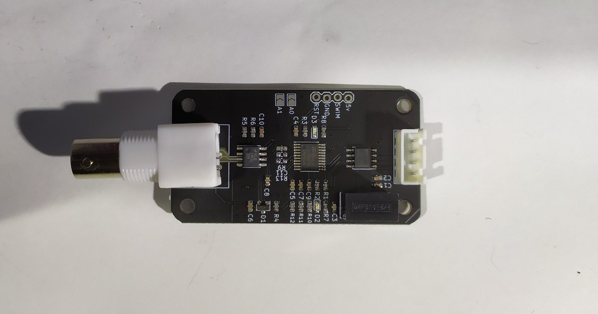
Isolated pH Probe Interface for reef-pi by ML Reefkeeping on Tindie
Read pH over I2C with Arduino or Raspberry Pi
Last edited:
What're the plugs that one would need for daisy-chaining these and for connecting to the ph probes?
I'm ordering up a hat and one of these boards tonight, and want to pick up the other parts.
I already have a stack of DS18B20s from some earlier brewing projects.
Do you still need one of these for ph probes with the goby hat?

Isolated pH Probe Interface for reef-pi by ML Reefkeeping on Tindie
Read pH over I2C with Arduino or Raspberry Piwww.tindie.com
Yes you still need the PH board. HAT does not have a PH circuit built into it.
Similar threads
- Replies
- 1
- Views
- 62
- Replies
- 10
- Views
- 301


