Need help with how to connect a Gavazzi water level sensor to an Arduino

GlassReef

Community Member
View Badges
Joined
Aug 17, 2009
Messages
27
Reaction score
14
Location
Weeki Wachee, FL
Rating - 0%
0   0   0
I am building and ATO-AWC (auto top off and water change) device. I have liquid level sensors from Gavazzi, model VP02EP. My problem is I have no idea how to connect them to an Arduino. Here is some of the data sheet:

VP02EP-2.jpg


VP02EP.jpg

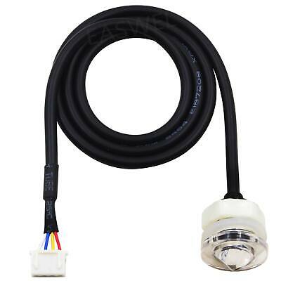
The attached cable has 3 wires: Brown (BN), Black (BK), and Blue (BU)
Looks like a simple diagram, but I have no idea how to implement it. Any help would be great!

Here's a link to the full datasheet:

DataSheet
 

Ron Reefman

Lets Go Snorkeling!
View Badges
Joined
Aug 12, 2012
Messages
9,284
Reaction score
20,887
Location
SW Florida
Rating - 0%
0   0   0
bump
 

Asmolupers

Community Member
View Badges
Joined
Dec 14, 2019
Messages
34
Reaction score
11
Rating - 0%
0   0   0
Did you figure this out? It appears to have a pull-up resistor between black and blue. That would make black the signal wire. This is a guess. The data sheet isn’t very detailed, especially for the cost of this sensor.
 

_AV

Well-Known Member
View Badges
Joined
Oct 3, 2019
Messages
679
Reaction score
695
Rating - 0%
0   0   0
Ouch at the price. Those are industrial sensors, perhaps a bit of an overkill depending on your application.
OP's example is a PNP output. This means that when it detects the state, it just puts the signal wire (BK) with the power wire (BN). So if you run the sensor off of a 12v PSU, you will measure 12v on the BK and BU wires when the sensor is closed.

The problem is that Arduino works off of 5v and the sensor's range is 10-40v. So you will need to drop the voltage on the BK wire down to 5v before it can go into arduino's analog input. This can be done with a couple of resistors to implement a voltage divider. But also have a common ground between the sensor power and arduino. Values for the resistors will depend on your power source for the sensor. For example to drop 12v to 5v, you can use 15k resistor to ground and 22k resistor to the power wire.

Here's a basic explanation:
 

Asmolupers

Community Member
View Badges
Joined
Dec 14, 2019
Messages
34
Reaction score
11
Rating - 0%
0   0   0
Ouch at the price. Those are industrial sensors, perhaps a bit of an overkill depending on your application.
OP's example is a PNP output. This means that when it detects the state, it just puts the signal wire (BK) with the power wire (BN). So if you run the sensor off of a 12v PSU, you will measure 12v on the BK and BU wires when the sensor is closed.

The problem is that Arduino works off of 5v and the sensor's range is 10-40v. So you will need to drop the voltage on the BK wire down to 5v before it can go into arduino's analog input. This can be done with a couple of resistors to implement a voltage divider. But also have a common ground between the sensor power and arduino. Values for the resistors will depend on your power source for the sensor. For example to drop 12v to 5v, you can use 15k resistor to ground and 22k resistor to the power wire.

Here's a basic explanation:

I assume you have experience with this sensor? The schematic shows a pull-up resistor between the output and +V. Does he need to add it to the circuit?

To the op, for FWIW, I’ve been using this one for a year with my nodemcu setup with no problems no problems. It will work with a 5v controller as well.


_AV

Well-Known Member
View Badges
Joined
Oct 3, 2019
Messages
679
Reaction score
695
Rating - 0%
0   0   0
I don't have experience with this particular sensor, but it's not different from any other industrial sensors. There is no pull up resistor for PNP outputs. You need one for NPN though. There is a pull down resistor for PNP, but the voltage divider already takes care of that.
 

Asmolupers

Community Member
View Badges
Joined
Dec 14, 2019
Messages
34
Reaction score
11
Rating - 0%
0   0   0
I don't have experience with this particular sensor, but it's not different from any other industrial sensors. There is no pull up resistor for PNP outputs. You need one for NPN though. There is a pull down resistor for PNP, but the voltage divider already takes care of that.

Yes, I understand how transistors work. The schematic just isn’t very clear and I’ve never seen that symbol on a drawing. Also, it would help if I looked at the right drawing. I was just trying to clear things up for the op, which hopefully, has been accomplished.
 
Last edited:

High pressure shells: Do you look for signs of stress in the invertebrates in your reef tank?

  • I regularly look for signs of invertebrate stress in my reef tank.

    Votes: 39 32.5%
  • I occasionally look for signs of invertebrate stress in my reef tank.

    Votes: 28 23.3%
  • I rarely look for signs of invertebrate stress in my reef tank.

    Votes: 23 19.2%
  • I never look for signs of invertebrate stress in my reef tank.

    Votes: 30 25.0%
  • Other.

    Votes: 0 0.0%
Back
Top