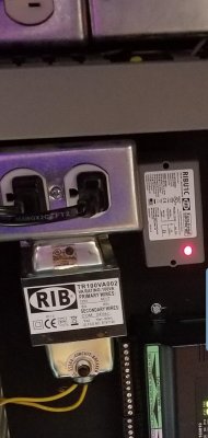
Outlet Saver (Aquarium Engineering Tank Saver, Relay outlet, Digital Aquatics Expansion Socket)

DBR_Reef

Active Member
View Badges
Joined
Apr 4, 2016
Messages
373
Reaction score
304
Location
Rochester, NY
Rating - 0%
0   0   0


How To Build a DIY Expansion Socket

Reasons to use one:

Save your energy bar- A energy bar is a lot more expensive than a single relay, and the relays in energy bars will wear out, especially if you are using them to switch higher loads

Take load off an outlet- If you are using an apex, then then your eb832 outlets have a max of 7 amps or 700w, and 15 amps or 1500 watts for the whole bar. The Old EB8s are 5 or 10 amps per outlet, and 15amps for the bar. You should probably use one of these if you use a large heater, chiller or larger halide lights.

Take load off a circuit- Then your circuit (the actual wiring of your house) probably has a 15- or 20-amp max. So you may want to have your energy bar on one circuit and some of the things it controls on a different circuit, to reduce draw on any one individual circuit. Or maybe you have an item that is more likely to trip a breaker or GFCI, and you want to put that on a different circuit.

Get an extra 2 outlets- if you have a EB823 by using the 2 24v accessory outlets to control the outlet saver.

So we are going to need:

A relay- A RIB2401B Power Relay is currently only $17 on amazon, and it comes with a box. These relays have a 24 Vac/dc/120 Vac Coil, which means we can use either the 24v accessory outlet or a 120v outlet to control it.

A outlet

A weatherproof box- preferably with ½ threaded connections

A liquid tight ½ npt cord connector

A power cord for the outlet- you could also directly wire this with romex or armored cable. Just make sure it is rated for the amps you are going to be drawing- to match the relay and be rated to 20amps, you need a 12gauge cord.

A signal cord- either a 120v cord or the apex 24v accessory cord, depending on which you are using

Construction:

Screw the waterproof box onto the RIB. Then insert the two cords into the strain relief.

Coil side: Take your signal cable and connect the positive or hot side to the correct cable, depending on if you are using 24v DC or 120v AC, and connect the ground or neutral to the coil common wire. Then shove those in the box.

Power side of the outlet: Connect the neutral of the power cord to the neutral side of the outlet, and the ground to the ground. Then we have the hot wire, and this is where the relay intercepts the circuit. The RIB relay comes with NC and NO contacts or wires- for most things we want normally open, or the outlet to fall back to off. So, take the NC wire and cap it off. Then we have to have to decide if we want to connect the hot wire to the common or the NO contact. I am of the opinion that connecting it to the NO contact is safer, as the NC contact is then never live, so I am going to wire it like that. So connect the hot wire of the cord to the NO wire, and connect the common wire to the hot side of the outlet. Then Then put it all into place and put on your cover plate- I made my own by cutting out a different plate because I could only find the cgfi plate covers with a flap cover, which I didn’t want.

That’s it, plug the signal cord into your apex and the power cable into whatever outlet you are using.
 

spllbnd2

Active Member
View Badges
Joined
Dec 1, 2014
Messages
178
Reaction score
117
Location
Edmonds, Washington
Rating - 0%
0   0   0
Question, Wouldn't you still be using the relay inside the controller to control this unit that you made? Or am I missing something here? Would you just simply use an always on outlet from the controller (apex or other)? A bit confused as it seems you would have 2 relays doing essentially the same thing.

Cheers,
Alex
 
OP
OP
DBR_Reef

DBR_Reef

Active Member
View Badges
Joined
Apr 4, 2016
Messages
373
Reaction score
304
Location
Rochester, NY
Rating - 0%
0   0   0
Question, Wouldn't you still be using the relay inside the controller to control this unit that you made? Or am I missing something here? Would you just simply use an always on outlet from the controller (apex or other)? A bit confused as it seems you would have 2 relays doing essentially the same thing.

Cheers,
Alex
Yes, you are using a relay to control a relay. However you are taking all the load off the relay in the apex powerbar and placing it on the relay in the expansion socket. The relays in the powerbar are rated at 7amps, and there are plenty of pieces of equipment that can exceed that rating. Even if you are somewhat close to that rating, relays take minor damage every time they turn on and off, with a little bit of the metal of the contact being ablated. The amount of damage is proportional to current through the relay. So by using an exterior relay we can extend the lifespan of the relay in the powerbar. But yes, the primary use for these is for higher loads.
 

Arricefe

Well-Known Member
View Badges
Joined
Nov 22, 2018
Messages
591
Reaction score
1,039
Location
San Antonio
Rating - 0%
0   0   0


How To Build a DIY Expansion Socket

Reasons to use one:

Save your energy bar- A energy bar is a lot more expensive than a single relay, and the relays in energy bars will wear out, especially if you are using them to switch higher loads

Take load off an outlet- If you are using an apex, then then your eb832 outlets have a max of 7 amps or 700w, and 15 amps or 1500 watts for the whole bar. The Old EB8s are 5 or 10 amps per outlet, and 15amps for the bar. You should probably use one of these if you use a large heater, chiller or larger halide lights.

Take load off a circuit- Then your circuit (the actual wiring of your house) probably has a 15- or 20-amp max. So you may want to have your energy bar on one circuit and some of the things it controls on a different circuit, to reduce draw on any one individual circuit. Or maybe you have an item that is more likely to trip a breaker or GFCI, and you want to put that on a different circuit.

Get an extra 2 outlets- if you have a EB823 by using the 2 24v accessory outlets to control the outlet saver.

So we are going to need:

A relay- A RIB2401B Power Relay is currently only $17 on amazon, and it comes with a box. These relays have a 24 Vac/dc/120 Vac Coil, which means we can use either the 24v accessory outlet or a 120v outlet to control it.

A outlet

A weatherproof box- preferably with ½ threaded connections

A liquid tight ½ npt cord connector

A power cord for the outlet- you could also directly wire this with romex or armored cable. Just make sure it is rated for the amps you are going to be drawing- to match the relay and be rated to 20amps, you need a 12gauge cord.

A signal cord- either a 120v cord or the apex 24v accessory cord, depending on which you are using

Construction:

Screw the waterproof box onto the RIB. Then insert the two cords into the strain relief.

Coil side: Take your signal cable and connect the positive or hot side to the correct cable, depending on if you are using 24v DC or 120v AC, and connect the ground or neutral to the coil common wire. Then shove those in the box.

Power side of the outlet: Connect the neutral of the power cord to the neutral side of the outlet, and the ground to the ground. Then we have the hot wire, and this is where the relay intercepts the circuit. The RIB relay comes with NC and NO contacts or wires- for most things we want normally open, or the outlet to fall back to off. So, take the NC wire and cap it off. Then we have to have to decide if we want to connect the hot wire to the common or the NO contact. I am of the opinion that connecting it to the NO contact is safer, as the NC contact is then never live, so I am going to wire it like that. So connect the hot wire of the cord to the NO wire, and connect the common wire to the hot side of the outlet. Then Then put it all into place and put on your cover plate- I made my own by cutting out a different plate because I could only find the cgfi plate covers with a flap cover, which I didn’t want.

That’s it, plug the signal cord into your apex and the power cable into whatever outlet you are using.

I may just have to return my "extra" EB832 I just ordered or sell it locally. I just "needed" one more controlled outlet, this is by far a more economical solution.
 

spllbnd2

Active Member
View Badges
Joined
Dec 1, 2014
Messages
178
Reaction score
117
Location
Edmonds, Washington
Rating - 0%
0   0   0
I see the relay that is used in this build is rated for well over 10,000,000 cycles. So it should last a lifetime. :D Not sure what the life cycles are on the controller relays.
 

cymonous

Active Member
View Badges
Joined
Apr 9, 2013
Messages
278
Reaction score
50
Location
Akron, OH
Rating - 0%
0   0   0
I have my own control system, not an apex. This is an outdated pic as I have changed and added some things. But, I did something similar with controlling my heaters.

Tank Heater Control.jpg
 
OP
OP
DBR_Reef

DBR_Reef

Active Member
View Badges
Joined
Apr 4, 2016
Messages
373
Reaction score
304
Location
Rochester, NY
Rating - 0%
0   0   0
I see the relay that is used in this build is rated for well over 10,000,000 cycles. So it should last a lifetime. :D Not sure what the life cycles are on the controller relays.
I have only heard a few complaints of powerbar relays failing, mostly with higher wattage heaters, and while I have not taken apart the newest EB832, I am sure that the relays are perfectly adequate. But they do have to pick fairly small relays to fit in the powerbar- and even neptune use to recommend buying an expansion socket for higher loads. Plus you can get the extra 2 outlets. And yes, the RIB relay is a beast :D
 

RobB'z Reef

2500 Club Member
View Badges
Joined
Apr 23, 2020
Messages
2,783
Reaction score
5,773
Location
Eau Claire
Rating - 0%
0   0   0


How To Build a DIY Expansion Socket

Reasons to use one:

Save your energy bar- A energy bar is a lot more expensive than a single relay, and the relays in energy bars will wear out, especially if you are using them to switch higher loads

Take load off an outlet- If you are using an apex, then then your eb832 outlets have a max of 7 amps or 700w, and 15 amps or 1500 watts for the whole bar. The Old EB8s are 5 or 10 amps per outlet, and 15amps for the bar. You should probably use one of these if you use a large heater, chiller or larger halide lights.

Take load off a circuit- Then your circuit (the actual wiring of your house) probably has a 15- or 20-amp max. So you may want to have your energy bar on one circuit and some of the things it controls on a different circuit, to reduce draw on any one individual circuit. Or maybe you have an item that is more likely to trip a breaker or GFCI, and you want to put that on a different circuit.

Get an extra 2 outlets- if you have a EB823 by using the 2 24v accessory outlets to control the outlet saver.

So we are going to need:

A relay- A RIB2401B Power Relay is currently only $17 on amazon, and it comes with a box. These relays have a 24 Vac/dc/120 Vac Coil, which means we can use either the 24v accessory outlet or a 120v outlet to control it.

A outlet

A weatherproof box- preferably with ½ threaded connections

A liquid tight ½ npt cord connector

A power cord for the outlet- you could also directly wire this with romex or armored cable. Just make sure it is rated for the amps you are going to be drawing- to match the relay and be rated to 20amps, you need a 12gauge cord.

A signal cord- either a 120v cord or the apex 24v accessory cord, depending on which you are using

Construction:

Screw the waterproof box onto the RIB. Then insert the two cords into the strain relief.

Coil side: Take your signal cable and connect the positive or hot side to the correct cable, depending on if you are using 24v DC or 120v AC, and connect the ground or neutral to the coil common wire. Then shove those in the box.

Power side of the outlet: Connect the neutral of the power cord to the neutral side of the outlet, and the ground to the ground. Then we have the hot wire, and this is where the relay intercepts the circuit. The RIB relay comes with NC and NO contacts or wires- for most things we want normally open, or the outlet to fall back to off. So, take the NC wire and cap it off. Then we have to have to decide if we want to connect the hot wire to the common or the NO contact. I am of the opinion that connecting it to the NO contact is safer, as the NC contact is then never live, so I am going to wire it like that. So connect the hot wire of the cord to the NO wire, and connect the common wire to the hot side of the outlet. Then Then put it all into place and put on your cover plate- I made my own by cutting out a different plate because I could only find the cgfi plate covers with a flap cover, which I didn’t want.

That’s it, plug the signal cord into your apex and the power cable into whatever outlet you are using.

You sir, are a flippin genius @DBR_Reef ! I just love this idea. After upgrading to 600w heaters (x2) on my tank I had to stop using my inkbird as it would exceed the outlet rating.

I currently (get it) have the heaters split between two different EB832's which are each on a separate 20amp circuit. I don't want to get a second inkbird because I'd prefer to have a single temp controller overseeing both heaters and I want to alternate the heaters throughout the day (12h on, 12h off). I'll keep the inkbird laying around as a backup and just use the Apex to control the heaters I think.

I have been watching the power usage and it appears it only switches the outlets around 12 times a day each (6 on, 6 off). That's only 4,300 cycles a year. I gotta think those Apex relays can support that rate for more than a few years... Just a hunch as I've seen no specs on the cycle ratings for them. Maybe you have some thoughts there?

One question I have is, are those 24v ports on the Apex controlled by their own relays as well? If so, are they as robust as the ones controlling the outlets? Trying to decide what the better route is. I like the idea of getting a couple free relayed outlets. I'd still keep the heaters split between two bars so I'm running them on separate circuits so I don't lose them all if one of them should trip while I'm away. I've programmed the Apex to light up the alternate if temps drop to far, the assumption being the currently active heater is non functional.

Thanks for this write up and the video, fantastic!
 
Last edited:
OP
OP
DBR_Reef

DBR_Reef

Active Member
View Badges
Joined
Apr 4, 2016
Messages
373
Reaction score
304
Location
Rochester, NY
Rating - 0%
0   0   0
Could this be used to switch to battery power during a power outage?
Yes, if you wanted a piece of equipment to come on during a power outage you could switch the normally closed and normally open wires, so that when power was lost it would switch to backup. If you want to switch a piece of equipment from wall power to backup power then a different type of relay would be best.
 

High pressure shells: Do you look for signs of stress in the invertebrates in your reef tank?

  • I regularly look for signs of invertebrate stress in my reef tank.

    Votes: 35 31.8%
  • I occasionally look for signs of invertebrate stress in my reef tank.

    Votes: 26 23.6%
  • I rarely look for signs of invertebrate stress in my reef tank.

    Votes: 21 19.1%
  • I never look for signs of invertebrate stress in my reef tank.

    Votes: 28 25.5%
  • Other.

    Votes: 0 0.0%
Back
Top