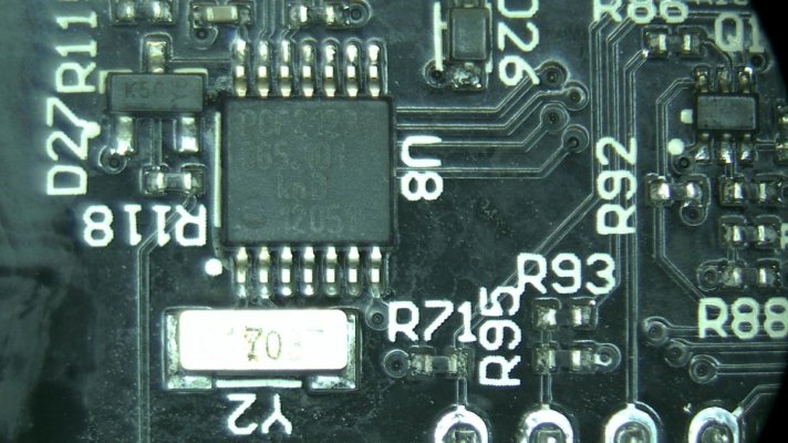
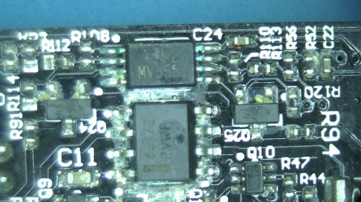
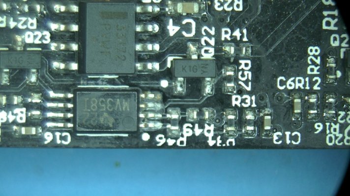
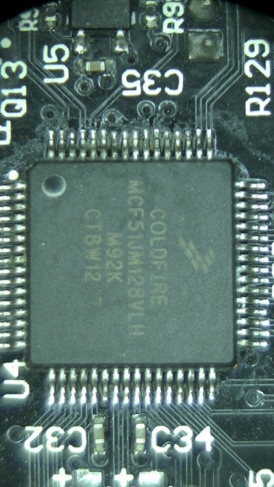
Radion XR30 complete no light repair

_AV

Well-Known Member
View Badges
Joined
Oct 3, 2019
Messages
679
Reaction score
694
Rating - 0%
0   0   0
My previous electronic equipment repairs

Radion XR15:

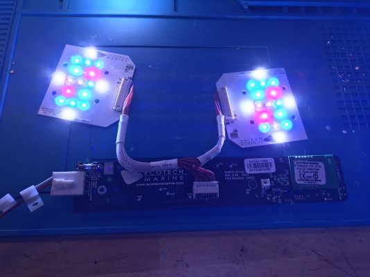
A fellow reefer mailed me their Ecotech Radion for repair service as it's long been out of warranty. The unit turns on briefly before shutting down and the fan is clean and spins perfectly fine.
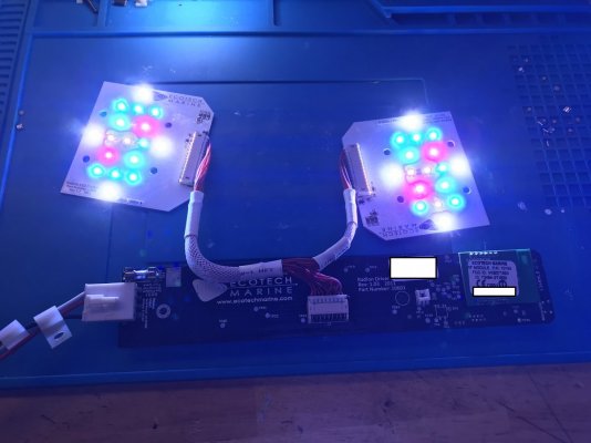
The light appears to be an XR30 Gen 1 with upgraded LED clusters. Let's begin with an initial visual inspection, shall we?
IMG_0306a.jpg


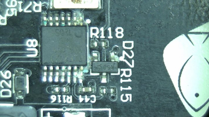
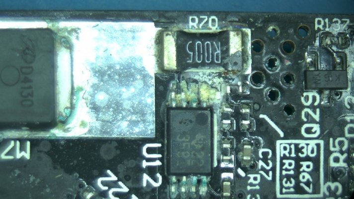
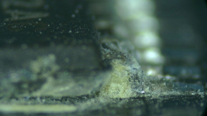
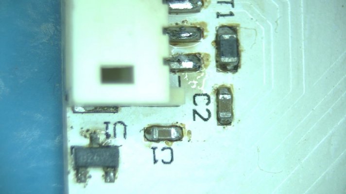
For an older light, one would expect a fair amount of corrosion on the main board. This light is certainly no exception.

0035.jpg

0001.jpg
0003.jpg

0004.jpg 0008.jpg

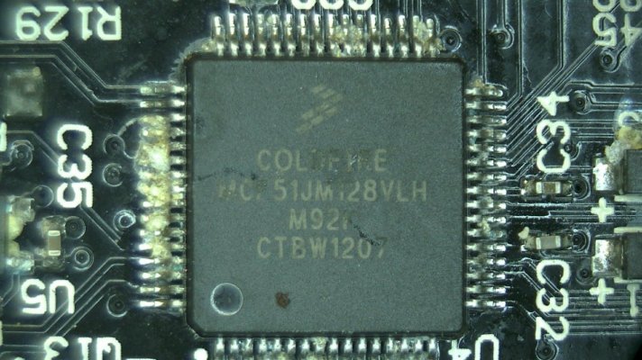
Even the main controller had a quite a bit of corrosion:
0010.jpg
0011.jpg

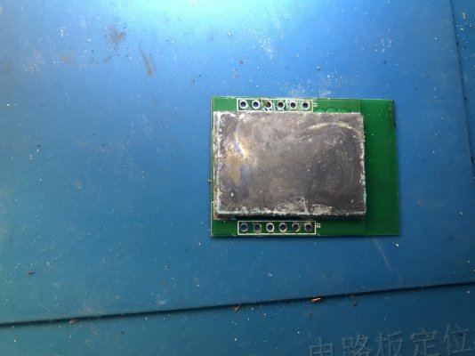
The wireless board was not in a much better shape:
0017.jpg

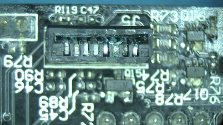
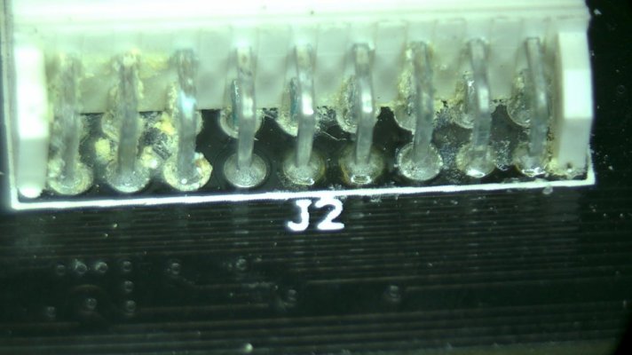
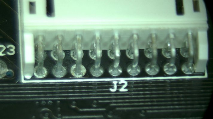
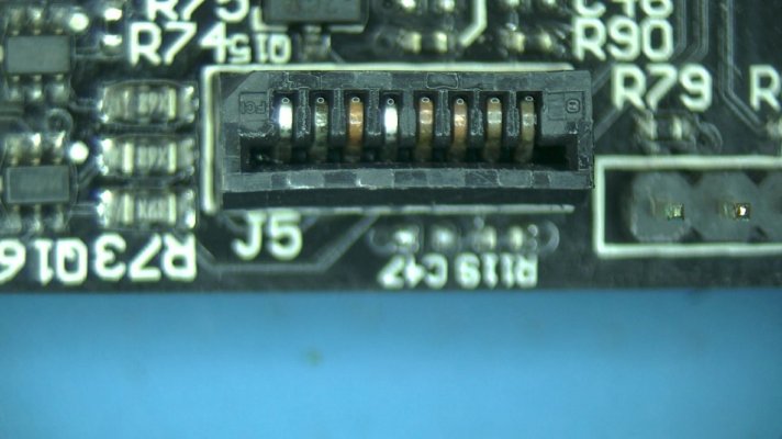
And all connectors were in a rough shape:
0006.jpg 0024.jpg

Now, all of this corrosion may not have been the primary cause of the failure, but leaving it on the board is going to be asking for trouble later. It's time to give the main board a bath (or two)!

First, the wireless chip needs to come off. We find more corrosion around and under the chip as well:
IMG_0302.JPG
0020.jpg


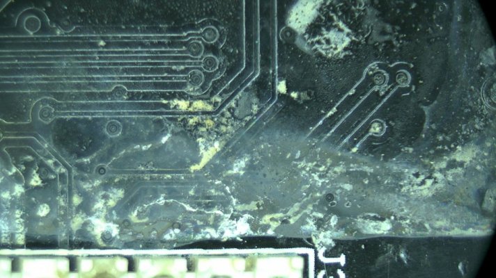
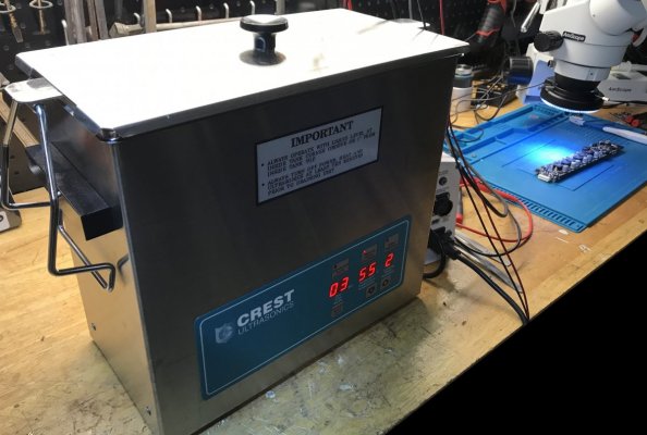
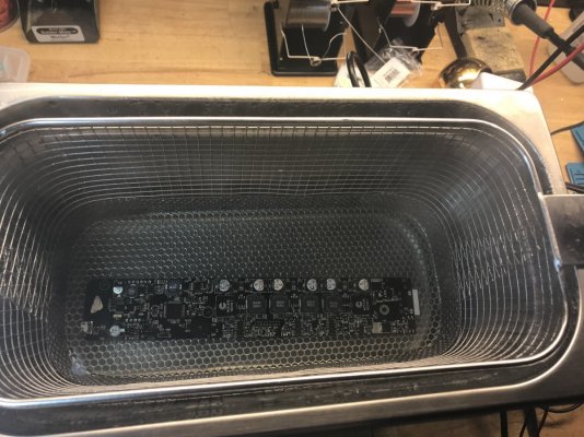
With the wireless module removed, the board is ready for a really good, but gentle ultrasonic cleaning:
IMG_0304a.jpg IMG_0307.JPG

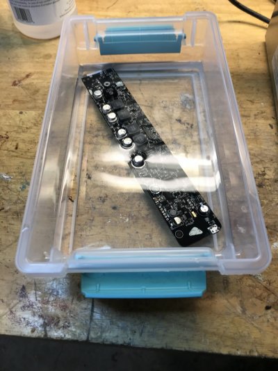
And a quick rinse to displace any cleaning solution on the board:
IMG_0310.JPG

Now let's see if the cleaning made any difference:

0004.jpg 0026.jpg

0001.jpg 0029.jpg

0010.jpg 0028.jpg

How about connectors:
0024.jpg 0032.jpg


0006.jpg 0025.jpg

I'd say, not bad for a quick rinse! But will the light work now? Not a chance. There is a bit more fun ahead!
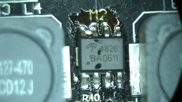
XR30 has 6 channels to control different sets of LEDs. Each channel is handled by a circuit of mosfets, op amps, relays and inductors. To save some space (and money) ecotech is using 3 dual mosfets, one to power two different LED channels. They look like so:
0044.jpg

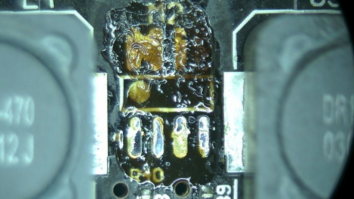
On this board, the middle mosfet shorted on both channels. This means at least 2/6 LED channels won't work unless it's replaced. Let's remove and replace:
0043.jpg

With the burned out mosfet replaced, the board is mostly happy again. In fact, it now works perfectly fine with a good known working set of LED clusters.
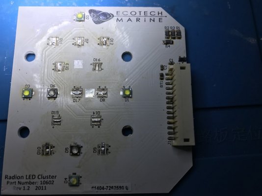
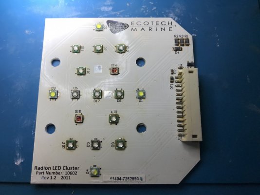
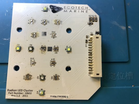
But the lights still won't fully turn on with the original LED lights. Time to examine the clusters. Oh, boy!

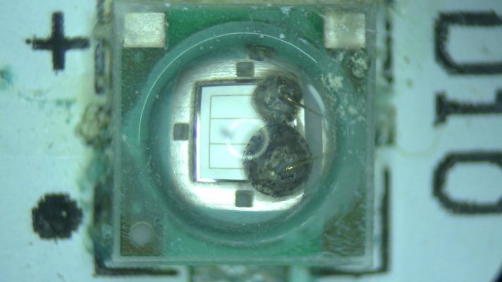
Of the total 32 LEDs across 2 clusters, 19 (!) were burned out or shorted. A typical picture observed:
0037.jpg 0038.jpg

0040.jpg 0041.jpg

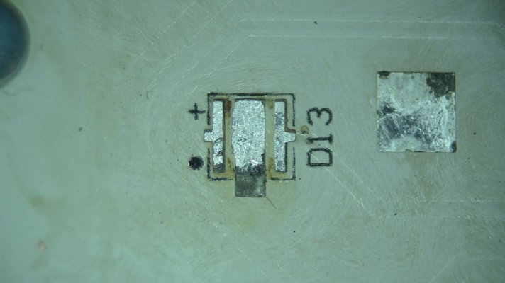
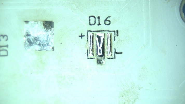
All of them will have to be replaced. There was certainly some corrosion under the LEDs:

IMG_0359.JPG

0045.jpg

But not anything that can't be fixed:
0046.jpg


IMG_0361.JPG

We are ready to do some baking:
IMG_0362.JPG

The final product:
IMG_0364.JPG

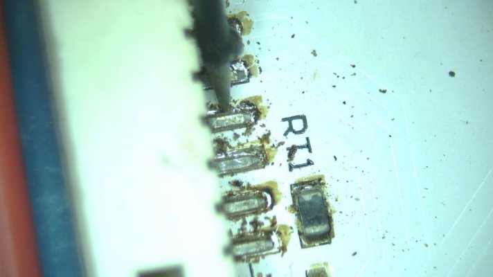
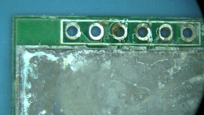
But wait, there is more! After connecting everything together, some LEDs would still not power on. It turns out that the main connector on the cluster has some pins disconnected due to age and corrosion. Here you can see I'm moving the pin with my pick:
0047.jpg

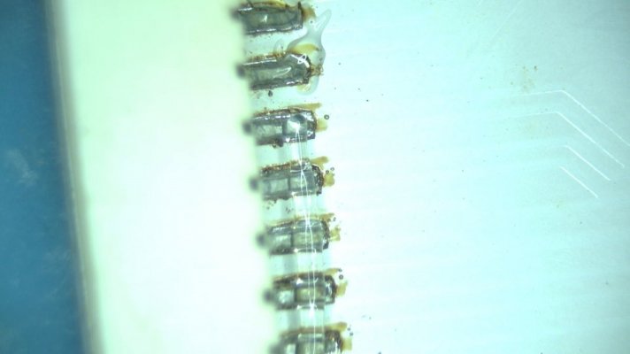
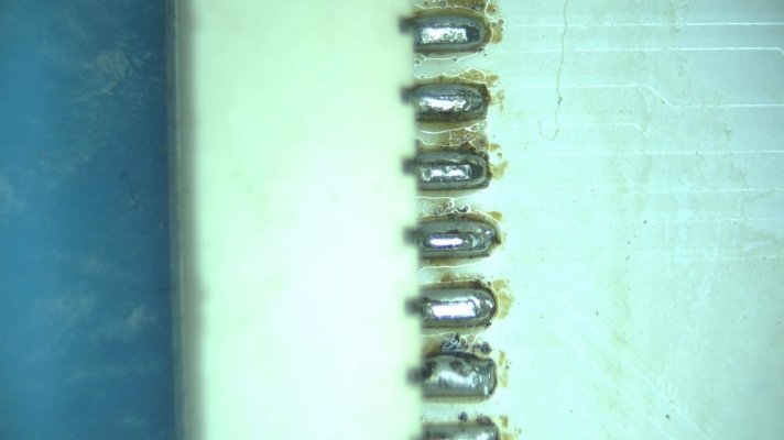
We'll clean up and reflow all the pins:


0048.jpg 0049.jpg

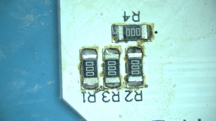
And while we are at it, we might as well touch up any other non LED components on the board:

0050.jpg 0051.jpg

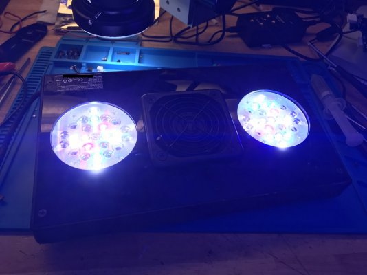
And with this, the light is working again!

IMG_0370a.jpg

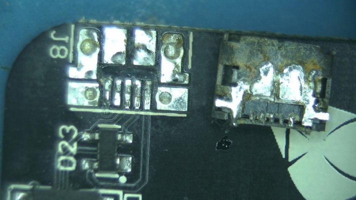
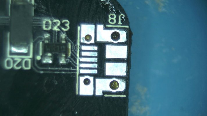
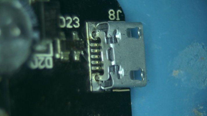
But there is even more! Despite a very good ultrasonic cleaner, the micro USB connector on the main board was corroded to the point it would not make a stable connection. Without the USB, connecting the unit to ecotech live is going to be a problem.

First, we'll remove the bad connector and clean up the pads:
0054.jpg 0055.jpg

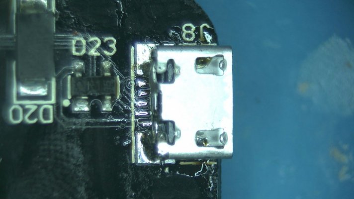
Put a brand new connector in place and solder it in.
0058.jpg 0057.jpg

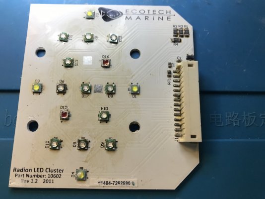
And with that, the complete repair of this old radion light is complete. It received many brand new LEDs, the majority of them are newer models with similar specs to the originals. They will provide even more intensity with less power consumption and will last longer. The board was thoroughly cleaned from corrosion and had a mosfet and the USB connector replaced.

IMG_0376a.jpg 0018.jpg IMG_0374.JPG
 

WallyB

REEF Techno-Geek
View Badges
Joined
Jan 24, 2017
Messages
3,127
Reaction score
8,093
Location
GTA Toronto, CANADA
Rating - 0%
0   0   0
Wow!! I mean WOW!!!

I bow to you in highest respect and admiration.

I do DIY building more than repair.... NEw Fresh Components.

I've done a lot of minor electronic repairs, but if I saw that board in that shape I wouldn't have even tried beyond a contact cleaner wash. Maybe a small SMB component like I did once for a Washing Machine Controller Board.

I admire the equipment you have and the dedication, persistance to go detailed and distance.

And TO SUCCEED it getting the Light working!! That's blew me away!

I actually got 6 XR30 Gen 1's handed down to me for free.
Bought a batch of new fans, since they were going one by one, which shut off the light due to overheat protection.
That got them all running.

The G1's are not G4's but they are perfect for my Hybrid T5 LED setups.

AGAIN!! Kudos to your percision and successful restore.
 

naterealbig

pea brain
View Badges
Joined
Sep 1, 2018
Messages
1,965
Reaction score
2,585
Location
Winter Garden
Rating - 100%
1   0   0
Incredible! Great job and detail.

Should I save your screen name for repairs for my Radions down the road? Or is this just a hobby for you?

Either way, thanks for sharing. I'm envious :)
 
OP
OP
_AV

_AV

Well-Known Member
View Badges
Joined
Oct 3, 2019
Messages
679
Reaction score
694
Rating - 0%
0   0   0
oh wow, thanks guys. I hope this information will be useful to someone. I wanted to show that these lights can be repaired, even with multiple points of failure. And that it's a fairly simple process with the right tools if you are know what to do.

On the equipment, I find it recently, given the current scale, that almost any electronics work requires significant magnification, precision, etc. All of that while my eyes are not getting any better. I actually use the equipment for very different type of electronics work, but found it to be dual purpose for repairs.

Should I save your screen name for repairs for my Radions down the road? Or is this just a hobby for you?
I am, in fact, experimenting with the idea of offering this type of repair service to the reefing community. This repair was done as a service. I find that the warranty on very expensive equipment is too short and limited. And even out of warranty repair is essentially a large component swap, such as the main board or an LED cluster. Which is then further limited by the availability of those assembled parts. If you have something worth repairing, DM me, I may be able to help.
 
Last edited:
OP
OP
_AV

_AV

Well-Known Member
View Badges
Joined
Oct 3, 2019
Messages
679
Reaction score
694
Rating - 0%
0   0   0
I've done a lot of minor electronic repairs, but if I saw that board in that shape I wouldn't have even tried beyond a contact cleaner wash. Maybe a small SMB component like I did once for a Washing Machine Controller Board.
A while back I wouldn't have touch this board as well. It does get easier with the right equipment and some practice. Yet, there are some things I would still not be able to fix, but generally, unless it's shredded, I can probably fix it.

If you liked this repair, wait until I eventually get to my backburner project: a Radion that went tank swimming while being powered and turned on. Here's a teaser of just one of many issues there:
0003.jpg
 

stefanm

Active Member
View Badges
Joined
Oct 11, 2017
Messages
360
Reaction score
397
Location
Sweden
Rating - 0%
0   0   0
Superb work there! Just wondering is there a way without special equipment that mortals can clean up the corrosion? Living in a humid tropical coastal are corrosion on PCB's is so common, constantly replacing boards of electronics or ditching the product gets expensive..
 
OP
OP
_AV

_AV

Well-Known Member
View Badges
Joined
Oct 3, 2019
Messages
679
Reaction score
694
Rating - 0%
0   0   0
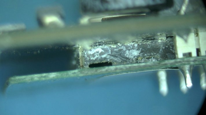
Thank you. This is actually an excellent question. Corrosion by itself is not as big of a problem as what it ends up doing to the electronic components. Corrosion often disrupts electrical connectivity between components. Thus, a mere corrosion cleanup will not bring the equipment back to life.
In this specific example you can see that one pin of the component is corroded to the point that the solder is gone and the copper is exposed.
1611167387591.png

What I failed to mention is that this was the cause of two LED channels to work intermittently. There was still a contact, but it could not carry as much current as it was designed for. Reflowing/resoldering the contact fixed that problem. Other similar examples include the main connector on the LED cluster, where at least 5-6 pins got disconnected from the board due to corrosion and also needed to be resoldered. And even the ultrasonic cleaner could not save the USB port, so it had to be replaced entirely.

So, once the equipment has failed due to corrosion, it is too late to clean it up and expect it to work again. Additional rework will be needed. However, it is feasible to proactively remove some corrosion or seal the pins so that they are corrosion resistant. In my other AI hydra repair, I showed how that can be done with some UV curable protective coating:

0026.jpg
0029.jpg


I think you would need to have an ultrasonic cleaner with proper cleaning solution to remove enough corrosion, even proactively. If you just soak it in the solution it will penetrate the surface, but will not shake it off entirely. Especially under and behind the pins as shown in the first picture above. Board components are just too small these days.
Protective coating application is easier, it still requires a real UV light and solder mask, but it's far cheaper than the ultrasonic cleaner. But the problem with being proactive is that it needs to be done early enough before corrosion sets it, yet the process will certainly void the warranty.
 
Last edited:

WallyB

REEF Techno-Geek
View Badges
Joined
Jan 24, 2017
Messages
3,127
Reaction score
8,093
Location
GTA Toronto, CANADA
Rating - 0%
0   0   0
My previous electronic equipment repairs

Radion XR15:

A fellow reefer mailed me their Ecotech Radion for repair service as it's long been out of warranty. The unit turns on briefly before shutting down and the fan is clean and spins perfectly fine.
The light appears to be an XR30 Gen 1 with upgraded LED clusters. Let's begin with an initial visual inspection, shall we?
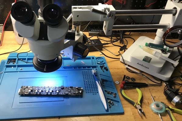
IMG_0306a.jpg

With the burned out mosfet replaced, the board is mostly happy again. In fact, it now works perfectly fine with a good known working set of LED clusters.
But the lights still won't fully turn on with the original LED lights. Time to examine the clusters. Oh, boy!

Of the total 32 LEDs across 2 clusters, 19 (!) were burned out or shorted. A typical picture observed:
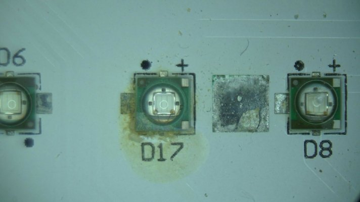
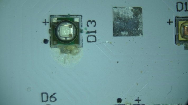
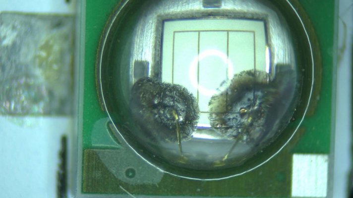
0040.jpg 0041.jpg

All of them will have to be replaced. There was certainly some corrosion under the LEDs:
IMG_0359.JPG

0045.jpg

But not anything that can't be fixed:
0046.jpg


IMG_0361.JPG

We are ready to do some baking:


And with that, the complete repair of this old radion light is complete. It received many brand new LEDs, the majority of them are newer models with similar specs to the originals. They will provide even more intensity with less power consumption and will last longer. The board was thoroughly cleaned from corrosion and had a mosfet and the USB connector replaced.
IMG_0376a.jpg

Hi @_AV ,

So I see you replaced all the Damaged LEDS on the G1 Radion and it worked.

I'm curious. As I mentioned I have a few Hand me Down G1's. All in good shape and working.

I was thinking could I replace some of the LED's with alternative LEDS to make the G1 like the G2, or G3.

What I was thinking (Just for fun, if possible) is replace some G1 LEDs with some Different LED to spice things up.

Couple of questions.

  • How difficult is it to remove the LED and how exactly did you do it?
  • What LED part numbers/models are the proper like-for-like replacement (Just Same Voltage and Current)
  • I do understand that if you replace a G1 3W Blue with the Exact Same 3W Blue LED it would work (what you did)
  • I also understand that The LED Current Driver on G1 doesn't have the same Capacity as a G2/G3
    • Thus I could not
      • replace a (5W) Cool White on the G1
      • with G3 Type LED: UV: 4 SemiLEDs (10W)
    • However I COULD possibly replace a
      • Cree G1: XP-E Royal Blue LEDs run at (3w) each
      • with a G3: Yellow: 2 Osram Oslon SSL Yellow, 590nm (3w)

What are your thoughts?

I found this table from a Thread Post. http://www.reefcentral.com/forums/showthread.php?t=2371960

G1 (What I have)
•8x Cree XP-G Cool White LEDs run at 5w each
•8x Cree XP-E Blue LEDs run at 3w each
•10x Cree XP-E Royal Blue LEDs run at 3w each
•4x Cree XP-E Green LEDs run at 3w each
•4x Osram Oslon SSL Hyper Red LEDs run at 3w each


G2
• White: 8 Cree XT-E Cool White (5W each)
• Red: 4 Osram Oslon SSL Hyper Red (3W each)
• Green: 4 Cree XP-E Green (3W each)
• Blue: 8 Cree XP-E Blue (3W each)
• Royal Blue: 8 Cree XT-E Royal Blue (5W each)
Max Wattage of Radion Fixture: 140 Watts
Max Wattage of LED Channels: 130 Watts

Pro
• White: 8 Cree XT-E Cool White (5w each)
• Red: 4 Osram Oslon SSL Hyper Red, 660nm (3w each)
• Yellow: 2 Osram Oslon SSL Yellow, 590nm (3w each)
• Green: 4 Cree XP-E Green, 520nm (3w each)
• Blue: 8 Cree XP-E Blue, 468nm (3w each)
• Royal Blue: 8 Cree XT-E Royal Blue, 442nm (5w each)
• Indigo: 4 SemiLEDs UV, 415nm (2.5w each)
• Ultraviolet: 4 SemiLEDs UV, 405nm (2.5w each)
Max Wattage of Radion Fixture: 170 Watts
Max Wattage of LED Channels: 155 Watts

G3
MAX PAR: 900
• Cool White: 8 Cree XT-E (40W)
• Deep Blue: 6 Osram Oslon Square (24W)
• Blue: 8 Cree XP-E (24W)
• Green: 4 Cree XP-E Green (14W)
• Hyper Red: 4 Osram Oslon SSL (12W)
• Indigo: 4 SemiLEDs (10W)
• UV: 4 SemiLEDs (10W)
WATTAGE
Variable Usage: 150W

G3 Pro
MAX PAR: 1100
• Cool White: 8 Cree XP-G2 (40W)
• Deep Blue: 8 Osram Oslon Square (40W )
• Blue: 8 Cree XP-E (24W)
• Green: 4 Cree XP-E (14W)
• Hyper Red: 4 Osram Oslon SSL (12W)
• Yellow: 2 Osram Oslon SSL (6W)
• Indigo: 4 SemiLEDs (10W)
• UV: 4 SemiLEDs (10W)
WATTAGE
Variable Usage: 170W
 
OP
OP
_AV

_AV

Well-Known Member
View Badges
Joined
Oct 3, 2019
Messages
679
Reaction score
694
Rating - 0%
0   0   0
Sure thing. Recall that gen 1 and gen 2 were at some point fully upgradable to gen 3 pro LED clusters. All you had to do is get a new set of clusters and the lens and swap them out.
Actually, ecotech wanted you to send your gen 1 in for a gen 3 pro upgrade citing significant hardware changes required.
Maybe I've never seen a board for the original Gen 1 radion, but from what I did see, all boards marked with 2011 on, all the way to gen 3 pro are almost identical (minor circuit changes around the MC). They certainly all have identical circuitry around all 6 channels of LED drivers.
This likely means that you can keep loading them up with more LEDs to your heart desire. So long as you don't exceed the capacity of the driver, or the gen 3 pro specs.

How difficult is it to remove the LED and how exactly did you do it?
It's not very difficult, but you have to be careful. You'd need a hot plate to warm the cluster board up from underneath. Some people literally use their stove and a skillet, but you risk overheating and burning off the pads. If that happens, heat dissipation from the LEDs will no longer work as intended. Once heated to the right temperature, LEDs should come off fairly easily. Then you'd need some wick, fresh flux and solder to remove old solder and prep the pads. Then you place the new LEDs, heat up the board again wait for surface tension to take care of the rest. All of this needs quite a bit of practice. The center of the LED is for heat dissipation to the board. If you have to too much solder at the ends, the LED will float, but will never make a good contact with the board in the center. If you press on the LED squeezing out excess solder, you may short the pads.
What LED part numbers/models are the proper like-for-like replacement (Just Same Voltage and Current)
You don't have to find the exact match to the originals. In fact, you will likely not be able to find new LEDs from 2011 as most of them have been discontinued by now. Voltage, current, foot print, forward voltage and heat dissipation requirements should be considered. Otherwise, look for LED model changes across radion generations. For example Gen 1 used XP-G white, Gen 3 moved on to XT-E whites, which are a significant upgrade. There are many part numbers in the datasheet for each model. Pick anything you want, as long as you are happy with the color and the intensity.
I do understand that if you replace a G1 3W Blue with the Exact Same 3W Blue LED it would work (what you did)
I actually did upgrade the LEDs to an extent. As I can no longer buy exact parts used on these lights back in 2011.
I also understand that The LED Current Driver on G1 doesn't have the same Capacity as a G2/G3
  • Thus I could not
    • replace a (5W) Cool White on the G1
    • with G3 Type LED: UV: 4 SemiLEDs (10W)
  • However I COULD possibly replace a
    • Cree G1: XP-E Royal Blue LEDs run at (3w) each
    • with a G3: Yellow: 2 Osram Oslon SSL Yellow, 590nm (3w)
Can you snap a couple of good pictures of your Gen 1 driver? I wonder if the only difference between Gen 1 and newer is the lack of one channel.
Personally, I would not mess with drastically changing the color of each channel like that to maintain the correct spectrum, have proper channel control, etc. Instead, I'd keep blue as blue, white as white, but upgrade to newer LED technology.
 

WallyB

REEF Techno-Geek
View Badges
Joined
Jan 24, 2017
Messages
3,127
Reaction score
8,093
Location
GTA Toronto, CANADA
Rating - 0%
0   0   0
Can you snap a couple of good pictures of your Gen 1 driver? I wonder if the only difference between Gen 1 and newer is the lack of one channel.
Personally, I would not mess with drastically changing the color of each channel like that to maintain the correct spectrum, have proper channel control, etc. Instead, I'd keep blue as blue, white as white, but upgrade to newer LED technology.

Thanks for your reply.......

Here you go....
I have 2 XR30's spare collecting dust, so easy to get some photo's.

XR30-Gen1-Cluster.jpg

The Cluster Looks very Similar to yours.

Here is the Driver Board.

XR30-Gen1-DriverBoardFront.jpg


and other side.

XR30-Gen1-DriverBoardBack.jpg


Except for the Fan's they all look in good shape.

I have no pressing need to change working LED's but with 2 spare XR30's....Just something to consider when I'm bored.

I'm not trying to break the units on purpose, since they might come in Handy to light up a QT or whatever.
They are Decent lights. You don't get Power Supplies as well built as the original all metal enclosures.

So I'd have to be really bored to attempt a LED Swap.
 

AZMSGT

2500 Club Member
View Badges
Joined
May 6, 2019
Messages
3,988
Reaction score
7,894
Rating - 0%
0   0   0
I just came across this posting and I can say one thing.. RESPECT.. I was 2M certified for the AF. Judging by your avatar and work that you are doing I'm guessing you are a 2M guy as well.

All hail the PRC 2000... LOL
 

WallyB

REEF Techno-Geek
View Badges
Joined
Jan 24, 2017
Messages
3,127
Reaction score
8,093
Location
GTA Toronto, CANADA
Rating - 0%
0   0   0
It's not very difficult, but you have to be careful. You'd need a hot plate to warm the cluster board up from underneath. Some people literally use their stove and a skillet, but you risk overheating and burning off the pads. If that happens, heat dissipation from the LEDs will no longer work as intended. Once heated to the right temperature, LEDs should come off fairly easily. Then you'd need some wick, fresh flux and solder to remove old solder and prep the pads. Then you place the new LEDs, heat up the board again wait for surface tension to take care of the rest. All of this needs quite a bit of practice. The center of the LED is for heat dissipation to the board. If you have to too much solder at the ends, the LED will float, but will never make a good contact with the board in the center. If you press on the LED squeezing out excess solder, you may short the pads.
Wow. I guesss you were not joking about using a Stove. We actually do have a Gas Element Stove in our Kitchen.


I do love this guys WAX CANDLE technique.

 
Last edited:
OP
OP
_AV

_AV

Well-Known Member
View Badges
Joined
Oct 3, 2019
Messages
679
Reaction score
694
Rating - 0%
0   0   0
Here is the Driver Board.

XR30-Gen1-DriverBoardFront.jpg


and other side.

XR30-Gen1-DriverBoardBack.jpg


Except for the Fan's they all look in good shape.

I have no pressing need to change working LED's but with 2 spare XR30's....Just something to consider when I'm bored.

I'm not trying to break the units on purpose, since they might come in Handy to light up a QT or whatever.
They are Decent lights. You don't get Power Supplies as well built as the original all metal enclosures.

So I'd have to be really bored to attempt a LED Swap.
This is a 2012 version board. I can clearly see all 6 LED channels circuits on the board and they all seem to be identical to any other boards I've seen from that time. Which leads me to believe that the driver should handle LEDs up to the gen 3 pro configuration.
 
OP
OP
_AV

_AV

Well-Known Member
View Badges
Joined
Oct 3, 2019
Messages
679
Reaction score
694
Rating - 0%
0   0   0
I just came across this posting and I can say one thing.. RESPECT.. I was 2M certified for the AF. Judging by your avatar and work that you are doing I'm guessing you are a 2M guy as well.

All hail the PRC 2000... LOL
Haha, I'm not officially an M2, but have certainly heard of the program! ;)
PRC 2000 was an amazing workhorse! I'm on hakko gear currently.
 

WallyB

REEF Techno-Geek
View Badges
Joined
Jan 24, 2017
Messages
3,127
Reaction score
8,093
Location
GTA Toronto, CANADA
Rating - 0%
0   0   0
This is a 2012 version board. I can clearly see all 6 LED channels circuits on the board and they all seem to be identical to any other boards I've seen from that time. Which leads me to believe that the driver should handle LEDs up to the gen 3 pro configuration.
Cool.

Maybe one day I'll consider upgrading one of my XR30's.
Just for fun.

Might do it sooner than later.

So you mentioned that there are specs for the Various LED's used for the Radion Gens.
Where can I find the exact specs?

I found that G1-G3 list, and I guess I just google for example (4 Cree XP-E) to looking the LED, Maker and XP-E series.
Correct?

You mentioned that you see 6 LED CHannels on the driver Board.
When I go into the Echosmart App I only get 5 Channels.
XR30-Slider.jpg


I there is some SW/FIrmware change needed to make the 6th Channel Active.
Most likely something only Echotech knows how to do.
Might even require some HW work as well. I also assume my LED Cluster is a 5 Channel setup.
To get the 6th Channel a different cluster would have to be installed using the Same Driver Board.

Too pricey but I an upgrade Cluster is still up for sale online.
https://mksshop.de/epages/34ad456e-...56e-eaf1-4da6-b075-1420e40d098f/Products/4892

To you point, the Driver can handle more power than the Current LEDs draw so even with the Same Cluster, I may be able to improve the LEDs to some degree.
 
Last edited:
OP
OP
_AV

_AV

Well-Known Member
View Badges
Joined
Oct 3, 2019
Messages
679
Reaction score
694
Rating - 0%
0   0   0
So you mentioned that there are specs for the Various LED's used for the Radion Gens.
Where can I find the exact specs?

I found that G1-G3 list, and I guess I just google for example (4 Cree XP-E) to looking the LED, Maker and XP-E series.
Correct?
Yes, exactly. I have not actually seen the exact specs, but Ecotech at various times published make, model and wavelength specs for each light. From those, it's fairly straightforward to pick the right part number from available datasheets. There could be a slight variation, but it is minimal enough not to worry about the change in spectrum. Here's one such list: https://www.makersled.com/guides/led-recipes/

You mentioned that you see 6 LED CHannels on the driver Board.
When I go into the Echosmart App I only get 5 Channels.
XR30-Slider.jpg


I there is some SW/FIrmware change needed to make the 6th Channel Active.
Most likely something only Echotech knows how to do.
Might even require some HW work as well. I also assume my LED Cluster is a 5 Channel setup.
To get the 6th Channel a different cluster would have to be installed using the Same Driver Board.
In theory, and I still need to verify, the software/firmware is smart enough to detect the additional draw on the 6th channel and switch over to the "pro" version.
With that said, it is fairly straightforward to reflash the controller on the driver with a "pro" version of the firmware. ;) You would need a programming device for the microcontroller and a pro version image from another light. The hardware itself is identical, so it will not know the difference at all. I'll need to do a post on this at some point. Perhaps as a part of restoring the badly burned driver. The controller on it burned from the inside and will need to be replaced and reprogrammed.
 
Last edited:

SeaHorse-23

New Member
View Badges
Joined
Oct 29, 2021
Messages
8
Reaction score
0
Location
Miami
Rating - 0%
0   0   0
Yes, exactly. I have not actually seen the exact specs, but Ecotech at various times published make, model and wavelength specs for each light. From those, it's fairly straightforward to pick the right part number from available datasheets. There could be a slight variation, but it is minimal enough not to worry about the change in spectrum. Here's one such list: https://www.makersled.com/guides/led-recipes/


In theory, and I still need to verify, the software/firmware is smart enough to detect the additional draw on the 6th channel and switch over to the "pro" version.
With that said, it is fairly straightforward to reflash the controller on the driver with a "pro" version of the firmware. ;) You would need a programming device for the microcontroller and a pro version image from another light. The hardware itself is identical, so it will not know the difference at all. I'll need to do a post on this at some point. Perhaps as a part of restoring the badly burned driver. The controller on it burned from the inside and will need to be replaced and reprogrammed.
i know this is an old thread but is semileds found under a different name? , i cannot find that brand listed on mouser or digi-key or any site i need to find these 4 led diodes.

Indigo: 4 SemiLEDs (10W)
• UV: 4 SemiLEDs (10W)
 

oreo54

5000 Club Member
View Badges
Joined
Sep 18, 2017
Messages
5,586
Reaction score
3,439
Rating - 0%
0   0   0
i know this is an old thread but is semileds found under a different name? , i cannot find that brand listed on mouser or digi-key or any site i need to find these 4 led diodes.

Indigo: 4 SemiLEDs (10W)
• UV: 4 SemiLEDs (10W)
Are you referring to diodes like this?
You may need to just buy and desolder..
 

Clear reef vision: How do you clean the inside of the glass on your aquarium?

  • Razor blade

    Votes: 159 62.1%
  • Plastic scraper

    Votes: 68 26.6%
  • Clean-up crew

    Votes: 89 34.8%
  • Magic eraser

    Votes: 44 17.2%
  • Other

    Votes: 67 26.2%
Back
Top