Reef-Pi build for a tropical vivarium

Mandelstam

Well-Known Member
View Badges
Joined
Oct 29, 2017
Messages
688
Reaction score
1,117
Location
Malmö, Sweden
Rating - 0%
0   0   0
I had come quite a way in planning my first reef tank build when I found out that my landlord doesn't approve of aquariums, or at least they have pretty much unrealistic safety measures you have to have in place. So I was forced to switch my focus over to something that could fill its place, at least until I live somewhere where I could have a reef tank.

So I started building a large tropical vivarium. It's taken quite some time because, one, it's my first ever vivarium build, and two, of course I wanted to go big from the start. It measures 48"(wide)x48"(tall)x36"(deep). So it's been quite a journey with breaks to just stop and figure things out and find solutions to everything and experiment with hardscape building.

Now it's come to the point where I need to get the controller for the whole setup up and running. And of course I still wanted to base it on Reef-Pi.

Features that the controller will handle:

Power controller
  • Misting system (24V high pressure diaphragm pump)
  • Fogger (ultrasonic humidifier)
  • 2x pumps for separate dripwalls/water features
  • External ventilation (12V cpu fans)
  • Possible future heating
Monitoring
  • Humidity and temparature (2x DS18B20 + 1x SHT-31)
  • Water sensors for return sump and RO reservoir for the misting system
Light controller
  • PWM + Mosfet drivers for 10x 20W led strips and moonlight
Internal airflow
  • PWM controlled 140mm cpu fans. Looking to hopefully put together some PWM programs like there are for powerheads for some variation.

Some pictures of the vivarium build, next post I'll go over where I am at the moment with the controller. I should have all the parts and it's basically just wiring, soldering and setting up the software left. If you're not into vivariums just jump to the next post. :)

1601132490382.png


1601132575199.png


1601132640247.png


1601132743268.png


1601132858200.png
 
OP
OP
Mandelstam

Mandelstam

Well-Known Member
View Badges
Joined
Oct 29, 2017
Messages
688
Reaction score
1,117
Location
Malmö, Sweden
Rating - 0%
0   0   0
For the controller I started with the enclosure. I didn't really know how much space everything would need and I had a nice spot for it under the stand so I decided to make it big enough to not get cramped and where most components would fit so I didn't end up with multiple smaller boxes or enclosures.

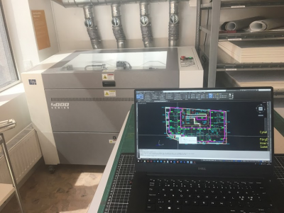
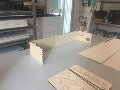
At work I have access to a laser cutter so I started to draw up the enclosure in cad and cut the parts out of 4mm plywood.

1601133401669.png


1601133623654.png


1601133834466.png


1601133509052.png


1601133546219.png


After painting the glued up enclosure the next step was to start all the AC wiring. I wanted to keep all the AC wiring separate within the enclosure so I got a couple of plastic electrical "boxes" to put both the 8 channel relay board and the rails where I needed to split up incoming AC.

Starting with the AC input.
1601134160336.png


1601134225839.png


For the AC outlets I was shopping around for quite some time for wall mounted outlets but oh my god they are pricey where I'm at. And then I got an idea to just use cable mounted female outlets instead. They will go out the top of the enclosure and hang down over one of the side walls of the stand and be accessible from the sump area.

1601134479942.png


A note on color coding and wires. Always color code. For your safety and others. I'm in Sweden and here standard color codes for AC are: yellow-green: Ground. Blue: Neutral. Brown: Hot.
The brown hot wires will go into the relay box.
1601134525549.png


So, the incoming AC goes into a small junction box. From there the hot wire is split up and they continue to the relay box. The neutral and ground wires from the outlets are connected here to the incoming AC.
1601134780953.png


The hot wires from the junction box was then connected to the relays. After that the hot wires from the outlets.
1601134963550.png


1601135130644.png


Now it's time to move on to the DC part of the build.
By the way, I'm not an electrician by any means and this is my first ever microcontroller build. My build won't make it to any "cabling ****" subreddit but I'll try and keep it as neat as possible. I bought some cable sleeves used in PC modding in different colors to both separate and gather up cables. Blue sleeve is for AC. I also have red, black, and white sleeves which I'll use in the build. I think I meant to use blue for signal cables and white for AC but I think I forgot haha! So white will have to be for signal cables.
1601135237985.png


Anyway, this is how far I've come up until now. I have some time to work on it tomorrow. Plan is to get rails for 5V, 12V and DC Ground up and ready. Maybe start on the mosfet drivers. 1601133609254.png 1601133672540.png
 
Last edited:
OP
OP
Mandelstam

Mandelstam

Well-Known Member
View Badges
Joined
Oct 29, 2017
Messages
688
Reaction score
1,117
Location
Malmö, Sweden
Rating - 0%
0   0   0
I have one question that I would be happy if anyone could help me with.

I'm using logic level mosfets to control my led lights. I went with the fet (IRLZ44NPBF) with the lowest Vgs(th) I could find and it's 1.0V. But still I'm not sure if it will be completely open at 3.3V. When reading the Adafruit tutorial on the PCA9685 it says that for the pin VCC: "

  • VCC - This is the logic power pin, connect this to the logic level you want to use for the PCA9685 output, should be 3 - 5V max! It's also used for the 10K pullups on SCL/SDA so unless you have your own pullups, have it match the microcontroller's logic level too!
Is there a way for me to get a 5V PWM from the board? From what I understand i'd need some kind of pullup in that case? How would I wire that up in that case? The only thing I understand from that is that I shouldn't just connect 5V to the VCC pin without doing something else...
 
OP
OP
Mandelstam

Mandelstam

Well-Known Member
View Badges
Joined
Oct 29, 2017
Messages
688
Reaction score
1,117
Location
Malmö, Sweden
Rating - 0%
0   0   0
You could search the forum for ReefPi there is a rather long thread. @Ranjib and others are the resident experts. I plan on using it along with RoboTank @robsworld78 for my first tank, soon. Good luck.

I'm following the main reef-pi thread already, thanks! :)

And good luck to you too!
 

robsworld78

Well-Known Member
View Badges
Joined
Feb 14, 2020
Messages
952
Reaction score
1,281
Location
Edmonton, Canada
Rating - 0%
0   0   0
I have one question that I would be happy if anyone could help me with.

I'm using logic level mosfets to control my led lights. I went with the fet (IRLZ44NPBF) with the lowest Vgs(th) I could find and it's 1.0V. But still I'm not sure if it will be completely open at 3.3V. When reading the Adafruit tutorial on the PCA9685 it says that for the pin VCC: "

  • VCC - This is the logic power pin, connect this to the logic level you want to use for the PCA9685 output, should be 3 - 5V max! It's also used for the 10K pullups on SCL/SDA so unless you have your own pullups, have it match the microcontroller's logic level too!
Is there a way for me to get a 5V PWM from the board? From what I understand i'd need some kind of pullup in that case? How would I wire that up in that case? The only thing I understand from that is that I shouldn't just connect 5V to the VCC pin without doing something else...

You should be fine with that mosfet, I've used various types similar and there was never an issue.

The PCA9685 outputs the VCC voltage, if it's powered with 5v it will output 5v on PWM pins. If I remember correctly the problem with that is the I2C will operate at 5v and if those lines are pulled to 3.3v the bus voltage will climb to around 3.9v, at least that was my experience.

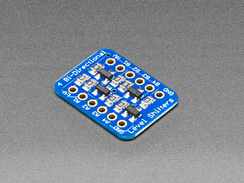
So if you want 5v PWM you'll need to use something like this to convert the I2C from 3.3v to 5v so it can go into the PCA9685.


As for pullups 10k is a little high although it would work, might be better to use 2.2k - 4.7k though.
 
OP
OP
Mandelstam

Mandelstam

Well-Known Member
View Badges
Joined
Oct 29, 2017
Messages
688
Reaction score
1,117
Location
Malmö, Sweden
Rating - 0%
0   0   0
You should be fine with that mosfet, I've used various types similar and there was never an issue.

The PCA9685 outputs the VCC voltage, if it's powered with 5v it will output 5v on PWM pins. If I remember correctly the problem with that is the I2C will operate at 5v and if those lines are pulled to 3.3v the bus voltage will climb to around 3.9v, at least that was my experience.

So if you want 5v PWM you'll need to use something like this to convert the I2C from 3.3v to 5v so it can go into the PCA9685.


As for pullups 10k is a little high although it would work, might be better to use 2.2k - 4.7k though.

Ah, ok! Thanks for the input on the mosfet! I'll see how it works on 3.3V before trying to play around with the VCC pin on the PCA9685.

It was a struggle finding mosfets that will work on 3.3V. I've heard people talking about mosfets with a Vgs(th) as low as 0.5-0.7V but I've never seen one.

Sorry... a reef VIVARIUM?!?! That’s the most amazing thing I’ve ever heard of!!! What’s the livestock list looking like???

Haha, sorry to disappoint, it's only going to be a vivarium, without the reef... Unfortunately. A reef vivarium sounds sweet! Mossy epiphyte filled branches hanging out over a white sandy lagoon..

Livestock is not decided yet but probably some Ranitomeya dartfrog together with some micro gecko. And maybe vampire crabs.

This is looking epic :) .
pcs9685 will output 5v pwm if you feed 5v in vcc

Thanks Ranjib!
And yes I figured that, it's the pull up that I'm confused about. Are they talking about the I2C pullups?

So if I put in pull up resistors on the SCL/SDA coming from the Pi, there's no problem feeding 5V into VCC?
 

theatrus

Valuable Member
View Badges
Joined
Mar 26, 2016
Messages
1,955
Reaction score
3,355
Location
Sacramento, CA area
Rating - 0%
0   0   0
Ah, ok! Thanks for the input on the mosfet! I'll see how it works on 3.3V before trying to play around with the VCC pin on the PCA9685.

It was a struggle finding mosfets that will work on 3.3V. I've heard people talking about mosfets with a Vgs(th) as low as 0.5-0.7V but I've never seen one.

Vgs is not binary sadly - physics apply. You can get FETs which start switching at 0.9V or so, but they would have a much higher Rdson than at say 5V. If all you need is level translation, then you can more or less ignore Rdson, but its bad news for a high power switch.

(You can also use FETs are linear components equally like a BJT, but the vast majority aren't designed for it so don't try to make a linear amplifier out of it without understanding SOAs and all that stuff).

So if I put in pull up resistors on the SCL/SDA coming from the Pi, there's no problem feeding 5V into VCC?

The pull-ups should be to 3.3V (or else you will damage the RPI), but the part can happily run at 5V. The I2C high transition level is around 0.7V, so there is plenty of room for a lower I2C bus voltage.

1601191189247.png
 
OP
OP
Mandelstam

Mandelstam

Well-Known Member
View Badges
Joined
Oct 29, 2017
Messages
688
Reaction score
1,117
Location
Malmö, Sweden
Rating - 0%
0   0   0
Vgs is not binary sadly - physics apply. You can get FETs which start switching at 0.9V or so, but they would have a much higher Rdson than at say 5V. If all you need is level translation, then you can more or less ignore Rdson, but its bad news for a high power switch.

(You can also use FETs are linear components equally like a BJT, but the vast majority aren't designed for it so don't try to make a linear amplifier out of it without understanding SOAs and all that stuff).


The pull-ups should be to 3.3V (or else you will damage the RPI), but the part can happily run at 5V. The I2C high transition level is around 0.7V, so there is plenty of room for a lower I2C bus voltage.

1601191189247.png

Thanks a lot for replying!

Just to make sure I understood everything. If I connect 5V to VCC on the PCA9685 board and put in pull ups (4.7kOhm?) to 3.3V, everything should be safe and fine and I'll get a 5V PWM from the board?
 

theatrus

Valuable Member
View Badges
Joined
Mar 26, 2016
Messages
1,955
Reaction score
3,355
Location
Sacramento, CA area
Rating - 0%
0   0   0
Thanks a lot for replying!

Just to make sure I understood everything. If I connect 5V to VCC on the PCA9685 board and put in pull ups (4.7kOhm?) to 3.3V, everything should be safe and fine and I'll get a 5V PWM from the board?

yup!

pull-ups can be in the range of 2.2k to 10k. 4.7k is a great middle ground.
 
OP
OP
Mandelstam

Mandelstam

Well-Known Member
View Badges
Joined
Oct 29, 2017
Messages
688
Reaction score
1,117
Location
Malmö, Sweden
Rating - 0%
0   0   0
Was out fishing with my son today so didn't have very much time to continue the build but managed to get some things done.

I soldered up the mosfet drivers for my lights. The main lights are 10 led 24V led strips, divided into pairs sharing a reflector/heatsink. Each pair is driven by one mosfet. The last mosfet will drive the moonlight which I have yet to purchase.

The cable coming in from the right is the ground from the 24v power supply. The 6 cables going out the back is going to connect up to the lights. The slightly smaller cable going out on the left will connect to the ground rail where ground is collected from the 5v and 12v power supplies. So all DC grounds are connected.

1601236140931.png


I also soldered up the rails for ground and 5v and 12v. The 12v will support some fans via LM2596 to get them not to run on full speed and more quiet. The enclosure will have a 80mm fan and then the vivarium will have some exhaust fans on top over the ventilation grill.
1601236436297.png


I also started to prototyping out a I2C rail where those devices can be hooked up. It would be neat to have open slots where you just connect the next one. You never know what the devs will add support for next haha! ;) This would be for the SDA and SCL lines and would be able to fit 6 I2C devices. 4.7k pull ups going to 3.3v.
Let me know if you see anything weird or wrong with this. Trying to wrap my head around the preferred way of connecting I2C devices. Star topology (no no), daisy chain, etc.
1601236653713.png
 

robsworld78

Well-Known Member
View Badges
Joined
Feb 14, 2020
Messages
952
Reaction score
1,281
Location
Edmonton, Canada
Rating - 0%
0   0   0
OP
OP
Mandelstam

Mandelstam

Well-Known Member
View Badges
Joined
Oct 29, 2017
Messages
688
Reaction score
1,117
Location
Malmö, Sweden
Rating - 0%
0   0   0
I kind of messed up my previous reply, what I was trying to say is if you connect a board like this and power it up with 5v the pullup resistors on it will pull SCL/SDA to 5v and the others you add will try to pull to 3.3v and this will result in around 3.9v on the I2C bus. Sounds like if you remove the pullups on breakout board it'll be ok.


You mean physically remove the pullups on the PCA-board?
 

robsworld78

Well-Known Member
View Badges
Joined
Feb 14, 2020
Messages
952
Reaction score
1,281
Location
Edmonton, Canada
Rating - 0%
0   0   0
This is the schematic for the Adafruit board, the bottom resistors circled are 10k on SCL/SDA being pulled up to VCC which will be 5v, they will fight the other pullups at 3.3v and settles near the middle is my experience.

So yeah to get 3.3v you need to remove them or use a logic level converter otherwise the Pi will be getting to much voltage. They use an array of 4 resistors, the other 2 are being used for the I2C address so removing them won't hurt anything just change the I2C address from default.

pca9685.jpg
 
OP
OP
Mandelstam

Mandelstam

Well-Known Member
View Badges
Joined
Oct 29, 2017
Messages
688
Reaction score
1,117
Location
Malmö, Sweden
Rating - 0%
0   0   0
This is the schematic for the Adafruit board, the bottom resistors circled are 10k on SCL/SDA being pulled up to VCC which will be 5v, they will fight the other pullups at 3.3v and settles near the middle is my experience.

So yeah to get 3.3v you need to remove them or use a logic level converter otherwise the Pi will be getting to much voltage. They use an array of 4 resistors, the other 2 are being used for the I2C address so removing them won't hurt anything just change the I2C address from default.

pca9685.jpg

Thanks for clarifying! My desoldering skills are not up to par for a challenge like that I think though... Not even sure I can identify those 4 resistors on the board to be honest. I think I'll be fine with 3.3v pwm, at least I hope I will. But thanks for not letting me damage anything by hooking up something I shouldn't!
 

robsworld78

Well-Known Member
View Badges
Joined
Feb 14, 2020
Messages
952
Reaction score
1,281
Location
Edmonton, Canada
Rating - 0%
0   0   0
Thanks for clarifying! My desoldering skills are not up to par for a challenge like that I think though... Not even sure I can identify those 4 resistors on the board to be honest. I think I'll be fine with 3.3v pwm, at least I hope I will. But thanks for not letting me damage anything by hooking up something I shouldn't!

I was looking at an image of the board but doesn't look like they gave the resistor array an identifier so a little hard to know for sure without a continuity test. It's one part and really not that hard to remove, just alternate heating both sides quickly and it'll eventually slide off. :)

You could use something like this if you want 5v and not remove the resistor.


I don't think it would damage the Pi immediately as it isn't too high of voltage but long term it could.

EDIT: Pretty sure it's the resistors I circled as it looks like two go to ground and 2 to VCC.

pca9685-2.jpg
 
Last edited:

Algae invading algae: Have you had unwanted algae in your good macroalgae?

  • I regularly have unwanted algae in my macroalgae.

    Votes: 14 30.4%
  • I occasionally have unwanted algae in my macroalgae.

    Votes: 9 19.6%
  • I rarely have unwanted algae in my macroalgae.

    Votes: 4 8.7%
  • I never have unwanted algae in my macroalgae.

    Votes: 5 10.9%
  • I don’t have macroalgae.

    Votes: 13 28.3%
  • Other.

    Votes: 1 2.2%
Back
Top