Reef-Pi build for a tropical vivarium

OP
OP
Mandelstam

Mandelstam

Well-Known Member
View Badges
Joined
Oct 29, 2017
Messages
688
Reaction score
1,117
Location
Malmö, Sweden
Rating - 0%
0   0   0
I was looking at an image of the board but doesn't look like they gave the resistor array an identifier so a little hard to know for sure without a continuity test. It's one part and really not that hard to remove, just alternate heating both sides quickly and it'll eventually slide off. :)

You could use something like this if you want 5v and not remove the resistor.
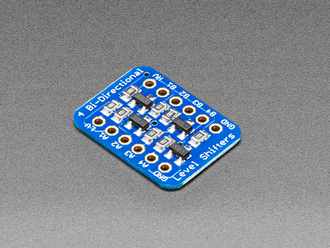

I don't think it would damage the Pi immediately as it isn't too high of voltage but long term it could.

EDIT: Pretty sure it's the resistors I circled as it looks like two go to ground and 2 to VCC.

pca9685-2.jpg
The level shifter sounds neat. I take it the LV side would be the 3.3v and the HV the 5v? 3.3v pwm from the PCA to A1-A4 and 5v pwm coming out on B1-B4? 5v to the HV pin? 3.3v to the LV?
1601283153951.png
 

robsworld78

Well-Known Member
View Badges
Joined
Feb 14, 2020
Messages
952
Reaction score
1,281
Location
Edmonton, Canada
Rating - 0%
0   0   0
The level shifter sounds neat. I take it the LV side would be the 3.3v and the HV the 5v? 3.3v pwm from the PCA to A1-A4 and 5v pwm coming out on B1-B4? 5v to the HV pin? 3.3v to the LV?
1601283153951.png

They do work good and you do connect 3.3v to LV and 5v to HV.

Everything on A side will be 3.3v so you would connect say A1 to Pi SCL and B1 to PCA9685 SCL.

And A2 to Pi SDA and B2 to PCA9685 SDA.
 
OP
OP
Mandelstam

Mandelstam

Well-Known Member
View Badges
Joined
Oct 29, 2017
Messages
688
Reaction score
1,117
Location
Malmö, Sweden
Rating - 0%
0   0   0
They do work good and you do connect 3.3v to LV and 5v to HV.

Everything on A side will be 3.3v so you would connect say A1 to Pi SCL and B1 to PCA9685 SCL.

And A2 to Pi SDA and B2 to PCA9685 SDA.

Ah, ok! And when I've connected it as you say above, I can safely connect 5v to VCC on the PCA9685 without having to worry about the pullups?
Sorry if I'm a bit slow when it comes to this haha!
 
OP
OP
Mandelstam

Mandelstam

Well-Known Member
View Badges
Joined
Oct 29, 2017
Messages
688
Reaction score
1,117
Location
Malmö, Sweden
Rating - 0%
0   0   0
@Ranjib, I'm tagging you in this question as you might know something about it.

I want to control a couple of 4-pin computer fans over pwm via the PCA9685 board. The issue is that 4-pin fans "need" a 25kHz pwm signal and the max frequency of the PCA9685 board is 1kHz. I've yet to try this myself but from what I've read is that at a lower frequency the fans get noisy and "clicky" as they are switched on/off. 25kHz is above the audible range of humans so at that frequency we don't hear it anymore.

The only workaround that I've come across is to use for example an Arduino where you can set the pwm frequency to 25kHz, let the Arduino read the pwm from the PCA9685 as an input and then output the same signal at 25kHz. I have an Arduino Uno lying around but the coding aspect is going to be a challenge for me so I just wanted to check before undertaking it, if you know of any other simpler way maybe that wouldn't require any coding.
 

robsworld78

Well-Known Member
View Badges
Joined
Feb 14, 2020
Messages
952
Reaction score
1,281
Location
Edmonton, Canada
Rating - 0%
0   0   0
Ah, ok! And when I've connected it as you say above, I can safely connect 5v to VCC on the PCA9685 without having to worry about the pullups?
Sorry if I'm a bit slow when it comes to this haha!

Yeah the PCA9685 module will be fine with 5v using the converter.
 
OP
OP
Mandelstam

Mandelstam

Well-Known Member
View Badges
Joined
Oct 29, 2017
Messages
688
Reaction score
1,117
Location
Malmö, Sweden
Rating - 0%
0   0   0
Not any big updates, a lot of stuff at work and not so much time at night to work on this but I did a few things.

I've soldered up most components and are working out the best placement of each inside the enclosure for cable management etc.

Most components now have soldered on connections (wires) and I'll either shorten them or solder on an extension as needed when I draw put the wires in place within the enclosure after the components are in place on their standoffs.
1601406718420.png


1601407013902.png


1601407034979.png
 
OP
OP
Mandelstam

Mandelstam

Well-Known Member
View Badges
Joined
Oct 29, 2017
Messages
688
Reaction score
1,117
Location
Malmö, Sweden
Rating - 0%
0   0   0
Yeah the PCA9685 module will be fine with 5v using the converter.

Sorry to bother you again man but I have a quick other question. The PCA9685 has internal pullup resistors accordning to the datasheet. Does that mean that if I put any other I2C devices after that board in a daisy chain I wouldn't need any other pull ups? I seem to recall to read somewhere that you only need one per chain. This is of course if I decide to run everything on 3.3v and don't get that level shifter.
 

theatrus

Valuable Member
View Badges
Joined
Mar 26, 2016
Messages
1,957
Reaction score
3,355
Location
Sacramento, CA area
Rating - 0%
0   0   0
Sorry to bother you again man but I have a quick other question. The PCA9685 has internal pullup resistors accordning to the datasheet. Does that mean that if I put any other I2C devices after that board in a daisy chain I wouldn't need any other pull ups? I seem to recall to read somewhere that you only need one per chain. This is of course if I decide to run everything on 3.3v and don't get that level shifter.
The PCA9685 doesn’t have on-chip pull-ups for SDA/SCL - are you talking about a carrier board that has them?

In general, there should only be one set of pull-ups on an I2C bus.

I2C levels allow for anything >0.7V to be considered a logic high - you can power the chip at 5V, but have the pull-ups to 3.3V without issue, meaning you do not need any level shifting.
 

robsworld78

Well-Known Member
View Badges
Joined
Feb 14, 2020
Messages
952
Reaction score
1,281
Location
Edmonton, Canada
Rating - 0%
0   0   0
Sorry to bother you again man but I have a quick other question. The PCA9685 has internal pullup resistors accordning to the datasheet. Does that mean that if I put any other I2C devices after that board in a daisy chain I wouldn't need any other pull ups? I seem to recall to read somewhere that you only need one per chain. This is of course if I decide to run everything on 3.3v and don't get that level shifter.

No worries. Where are you reading the PCA9685 has internal pullups? As @theatrus mentioned the actual chip doesn't have internal pullups that's why they add them on the module. Most chips don't have internals as it could mess with large designs.

One set of pullups on the lines is ideal but you can have multiple running in parallel. When 2 10k's are in parallel (two PCA9685 modules connected) you get 5k, if 3 10k's are in parallel you get 3.3k and it keeps going. This is why they use 10k on most modules as they figure it's likely another module will be added. If they used 4.7k it would drop to quick when others are added in parallel.


Don't let the value get to you though, what your doing will be fine no matter how you do it, just trying to explain. All you need to make sure is the voltage stays at 3.3v going to Pi.

@theatrus he's using the breakout module that does have pullups to VCC. If he powers it with 5v and has other resistors pulling up to 3.3v he'll end up with around 3.9v on bus. And if he doesn't have pullups going to 3.3v well you know what happens then. I think Pi can probably handle 3.9v but probably not good idea for long periods.
 
OP
OP
Mandelstam

Mandelstam

Well-Known Member
View Badges
Joined
Oct 29, 2017
Messages
688
Reaction score
1,117
Location
Malmö, Sweden
Rating - 0%
0   0   0
The PCA9685 doesn’t have on-chip pull-ups for SDA/SCL - are you talking about a carrier board that has them?

In general, there should only be one set of pull-ups on an I2C bus.

I2C levels allow for anything >0.7V to be considered a logic high - you can power the chip at 5V, but have the pull-ups to 3.3V without issue, meaning you do not need any level shifting.
No worries. Where are you reading the PCA9685 has internal pullups? As @theatrus mentioned the actual chip doesn't have internal pullups that's why they add them on the module. Most chips don't have internals as it could mess with large designs.

One set of pullups on the lines is ideal but you can have multiple running in parallel. When 2 10k's are in parallel (two PCA9685 modules connected) you get 5k, if 3 10k's are in parallel you get 3.3k and it keeps going. This is why they use 10k on most modules as they figure it's likely another module will be added. If they used 4.7k it would drop to quick when others are added in parallel.


Don't let the value get to you though, what your doing will be fine no matter how you do it, just trying to explain. All you need to make sure is the voltage stays at 3.3v going to Pi.

@theatrus he's using the breakout module that does have pullups to VCC. If he powers it with 5v and has other resistors pulling up to 3.3v he'll end up with around 3.9v on bus. And if he doesn't have pullups going to 3.3v well you know what happens then. I think Pi can probably handle 3.9v but probably not good idea for long periods.

Sorry if I wasn't clear, I'm talking about the Adafruit board, not the actual chip. They say there are 10k pullups from VCC to SDA/SCL (?).
https://learn.adafruit.com/16-channel-pwm-servo-driver/pinouts

I'll just to summarize what I think it is both of you have told me so far, I'd be happy if you could confirm.

  • I can power the board with 5v on the VCC pin as long as I put in pullups between SDA/SCL and 3.3v. With those pullups the Pi will only see 3.3v at the GPIO.
  • If I have more modules/links in the daisy chain I can add pullups for every link in the chain so the value doesn't drop too low.
Thanks again for your help! Much appreciated.
 

theatrus

Valuable Member
View Badges
Joined
Mar 26, 2016
Messages
1,957
Reaction score
3,355
Location
Sacramento, CA area
Rating - 0%
0   0   0
I can power the board with 5v on the VCC pin as long as I put in pullups between SDA/SCL and 3.3v. With those pullups the Pi will only see 3.3v at the GPIO.

Correct. In this case, you would need to remove the pull-ups on the PCA9685 adapter board, as all pull-ups should go to no more than 3.3V. There are a few techniques for quickly whacking off surface mount resistors - however I don't see pull-ups on this board for SDA and SCL?


If I have more modules/links in the daisy chain I can add pullups for every link in the chain so the value doesn't drop too low.

You _can_, but generally shouldn't. More is not better here.
 
OP
OP
Mandelstam

Mandelstam

Well-Known Member
View Badges
Joined
Oct 29, 2017
Messages
688
Reaction score
1,117
Location
Malmö, Sweden
Rating - 0%
0   0   0
Correct. In this case, you would need to remove the pull-ups on the PCA9685 adapter board, as all pull-ups should go to no more than 3.3V. There are a few techniques for quickly whacking off surface mount resistors - however I don't see pull-ups on this board for SDA and SCL?


You _can_, but generally shouldn't. More is not better here.


@robsworld78 thought that it would be this unit here:
1601571150585.png
 

theatrus

Valuable Member
View Badges
Joined
Mar 26, 2016
Messages
1,957
Reaction score
3,355
Location
Sacramento, CA area
Rating - 0%
0   0   0
@robsworld78 thought that it would be this unit here:
1601571150585.png

Good eye, you are correct - the right two resistors of that pack die to SCL and SDA - I had just brushed them off as being connected to the address pins before counting the address pins.

Simplest way would be to cut the two traces with an exacto knife, and confirm its disconnected with a multi-meter. You can also remove the component but its a bit trickier with a single iron and a large multi-lead pack like that.

Cut either the two reds or the green and then no more pull-ups:

1601572643162.png
 

Ranjib

7500 Club Member
View Badges
Joined
Apr 16, 2016
Messages
9,843
Reaction score
17,058
Location
Pleasant Hill, Concord
Rating - 0%
0   0   0
@Ranjib, I'm tagging you in this question as you might know something about it.

I want to control a couple of 4-pin computer fans over pwm via the PCA9685 board. The issue is that 4-pin fans "need" a 25kHz pwm signal and the max frequency of the PCA9685 board is 1kHz. I've yet to try this myself but from what I've read is that at a lower frequency the fans get noisy and "clicky" as they are switched on/off. 25kHz is above the audible range of humans so at that frequency we don't hear it anymore.

The only workaround that I've come across is to use for example an Arduino where you can set the pwm frequency to 25kHz, let the Arduino read the pwm from the PCA9685 as an input and then output the same signal at 25kHz. I have an Arduino Uno lying around but the coding aspect is going to be a challenge for me so I just wanted to check before undertaking it, if you know of any other simpler way maybe that wouldn't require any coding.
Pi's own two pwm channels (generally GPIO 18 and 19) can provide upto 19.2 MHz. For more pwm pins, we have to support some kinda external IC. you can use arduino or something else, but all of that will require some coding/driver support. I think a simple 555 timer ic can generate upto 10KHz pwm signal. I'll look out for some pre made solutions.. keep us posted
 
OP
OP
Mandelstam

Mandelstam

Well-Known Member
View Badges
Joined
Oct 29, 2017
Messages
688
Reaction score
1,117
Location
Malmö, Sweden
Rating - 0%
0   0   0
Good eye, you are correct - the right two resistors of that pack die to SCL and SDA - I had just brushed them off as being connected to the address pins before counting the address pins.

Simplest way would be to cut the two traces with an exacto knife, and confirm its disconnected with a multi-meter. You can also remove the component but its a bit trickier with a single iron and a large multi-lead pack like that.

Cut either the two reds or the green and then no more pull-ups:

1601572643162.png

Thanks a million! Scraping/cutting traces off I can do, I don't think I would have had the stomach to try and desolder them. I'm getting better at soldering but tiny surface mounted stuff? Uh uh...:oops::oops:

Pi's own two pwm channels (generally GPIO 18 and 19) can provide upto 19.2 MHz. For more pwm pins, we have to support some kinda external IC. you can use arduino or something else, but all of that will require some coding/driver support. I think a simple 555 timer ic can generate upto 10KHz pwm signal. I'll look out for some pre made solutions.. keep us posted

I might try Pi's own channels, thanks for the tip. I've yet to actually try and run the fans off 1kHz inside the vivarium or at all so I don't know what the noise is going to be like. It might not be noticeable. *crossing my fingers*. I guess you go into the settings on the pi and change the frequency somewhere? I'll get back with questions about that after everything is set up in that case. :)
 
OP
OP
Mandelstam

Mandelstam

Well-Known Member
View Badges
Joined
Oct 29, 2017
Messages
688
Reaction score
1,117
Location
Malmö, Sweden
Rating - 0%
0   0   0
Soldering cables into the right length takes time haha! Next bigger project like this I'm going to buy a good crimping tool and empty dupont housings and crimps. And wire strippers...:rolleyes:

Layout and cable wiring/management is almost done. I put the Arduino Uno in there just to make room for it if I ever need it to solve the 25kHz pwm signal.
1601723299230.png


I put this little rail together to connect up the sensors. On the left is where the data line from the ds18b20 connects up. Pullup 4.7k to 3.3v. The VCC from the sensor will go to the 5v rail. I'm going to run quite long cables and I read that doing it like this should help with longer cable runs. And it should be safe for the Pi.

On the right the DHT31-D sensor(s) will hook up with SCL/SDA and 3.3v. The SDA/SCL is connected to the PCA9685 board which is connected to the Pi (not in the picture yet though).
1601723516607.png


On the front of the enclosure I'm going to have a few status leds for when different equipment is running. I got some 3mm green leds for that.
1601724005594.png


The leds will run on 5v and be connected to the output pins on the ULN2803 and so will light up whenever a signal is going to the relay board.
1601724190612.png
 

Algae invading algae: Have you had unwanted algae in your good macroalgae?

  • I regularly have unwanted algae in my macroalgae.

    Votes: 49 34.8%
  • I occasionally have unwanted algae in my macroalgae.

    Votes: 30 21.3%
  • I rarely have unwanted algae in my macroalgae.

    Votes: 11 7.8%
  • I never have unwanted algae in my macroalgae.

    Votes: 10 7.1%
  • I don’t have macroalgae.

    Votes: 36 25.5%
  • Other.

    Votes: 5 3.5%
Back
Top