
- Joined
- Oct 3, 2019
- Messages
- 679
- Reaction score
- 695
Can, except the apex is their own proto on top of a CAN physical layer. Mostly pretty annoying")
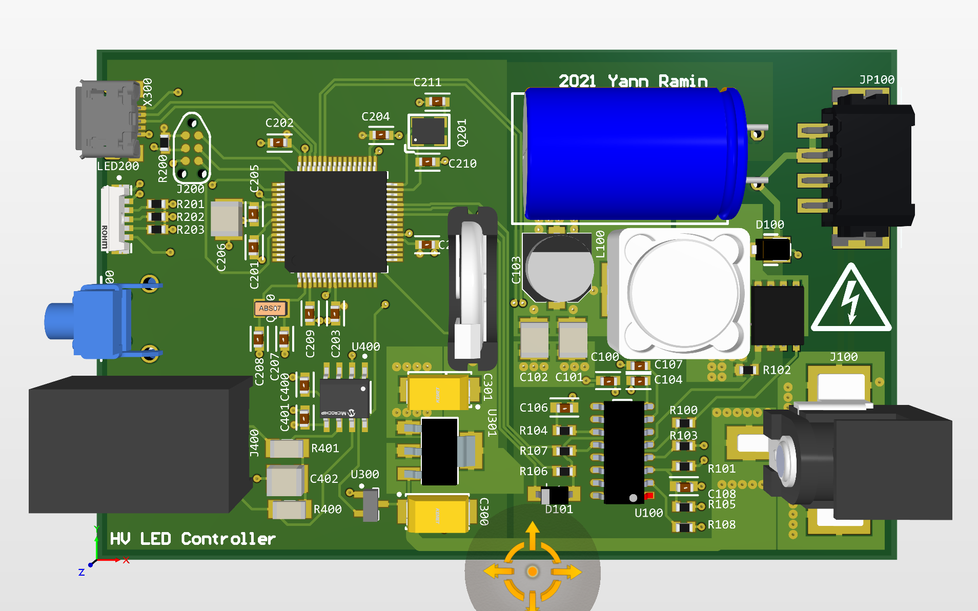
Ah yes. It certainly is. It's all on github though by now.
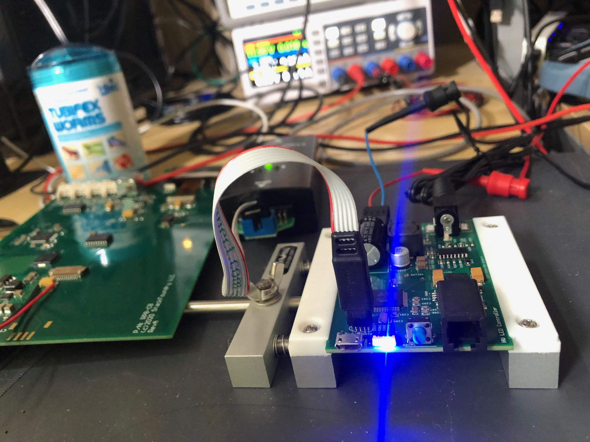
Your power bar even has the same number of outlets as an EB8.