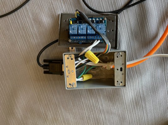
Reef-pi DIY power strip with relays

Michel

Community Member
View Badges
Joined
Nov 24, 2020
Messages
97
Reaction score
64
Location
The Netherlands
Rating - 0%
0   0   0
The Reef-pi documents are using an American DJ SR P8 power strip. Are there also people making the power strip themself?
I'm thinking about building a box with 8 power outlets and just use a 5V 8-relay board to switch one wire of each power outlet with the relays.
Than just connect the relay board to the RPi zero w by connecting 5V, Ground and 8 outlet pins and switch them on and off by the Reef-Pi.
Im thinking about wiring the relays NC (normaly closed) so the relays don't have to be powered on all the time (so the relays only turn on when I want to switch something off)

Is this a good or a bad idea? and are there other people who got something like this?
I would love to hear some input about this.
 

Paulo Hanashiro

Community Member
View Badges
Joined
Jun 4, 2013
Messages
32
Reaction score
19
Location
Sydney/Australia
Rating - 0%
0   0   0
I am using a TP-Link wireless power board for now (quick and easy deployment), but I'm also planning to do a relay board using the reef-pi guide #2 as the baseline.

I'm not and engineer, but I would not recommend to connect the relay board directly in the Pi. My plan is to either buy a Relay Pi hat with the required protections or use an Optocoupler to isolate the relay board from the Pi
 
OP
OP
Michel

Michel

Community Member
View Badges
Joined
Nov 24, 2020
Messages
97
Reaction score
64
Location
The Netherlands
Rating - 0%
0   0   0
I am using a TP-Link wireless power board for now (quick and easy deployment), but I'm also planning to do a relay board using the reef-pi guide #2 as the baseline.

I'm not and engineer, but I would not recommend to connect the relay board directly in the Pi. My plan is to either buy a Relay Pi hat with the required protections or use an Optocoupler to isolate the relay board from the Pi
Why shouldn't you wire the relays directly to the Raspberry Pi?
I got the board shown in the picture which is made for Arduino/Raspberry Pi.
I guess when it's made for eachother it should be safe right? Why would they sell it otherwise.

1627902061136.png
 

attiland

2500 Club Member
View Badges
Joined
Jul 22, 2020
Messages
2,594
Reaction score
4,800
Location
United Kingdom
Rating - 0%
0   0   0
Why shouldn't you wire the relays directly to the Raspberry Pi?
I got the board shown in the picture which is made for Arduino/Raspberry Pi.
I guess when it's made for eachother it should be safe right? Why would they sell it otherwise.

1627902061136.png
Opto isolation is to reduce the noise generated by the relays. For most part it doesn’t matter but some instruments like ph probes are sensitive and can read false when this kind of noise exists.
It also makes the circuit safer
 
OP
OP
Michel

Michel

Community Member
View Badges
Joined
Nov 24, 2020
Messages
97
Reaction score
64
Location
The Netherlands
Rating - 0%
0   0   0
Opto isolation is to reduce the noise generated by the relays. For most part it doesn’t matter but some instruments like ph probes are sensitive and can read false when this kind of noise exists.
It also makes the circuit safer
Yeah but Arduino/RPi relay boards like this already have optocouplers on them for this.
So by using a seperate board with external optocoupler you are just putting Optocoupler in series I guess which sounds pretty useless.

Aren't those "protection boards" not just for when you use relays not meant for arduino/RPi's?

20210802_144838.jpg
 

attiland

2500 Club Member
View Badges
Joined
Jul 22, 2020
Messages
2,594
Reaction score
4,800
Location
United Kingdom
Rating - 0%
0   0   0
Yeah but Arduino/RPi relay boards like this already have optocouplers on them for this.
So by using a seperate board with external optocoupler you are just putting Optocoupler in series I guess which sounds pretty useless.

Aren't those "protection boards" not just for when you use relays not meant for arduino/RPi's?

20210802_144838.jpg
If it already has it you don’t need an another one.
 

Ranjib

7500 Club Member
View Badges
Joined
Apr 16, 2016
Messages
9,843
Reaction score
17,056
Location
Pleasant Hill, Concord
Rating - 0%
0   0   0
Individual gpio has limit of 20ma, and pi overall has 80ma limits . So you can not draw more than this for your overall workload. The setup you mentioned is what we have used in past and it works, but it’s not optimal. As you add components things can pile up. It also depends on how you power pi (through gpio or through micro usb) .
I think it’s better to use a separate power source for the 5v pin and not pull it from pi gpio (5v). It is best to use a transistor in between gpio and relay pins (some relays like satin smart will have this already ).
 

Ranjib

7500 Club Member
View Badges
Joined
Apr 16, 2016
Messages
9,843
Reaction score
17,056
Location
Pleasant Hill, Concord
Rating - 0%
0   0   0
Yeah but Arduino/RPi relay boards like this already have optocouplers on them for this.
So by using a seperate board with external optocoupler you are just putting Optocoupler in series I guess which sounds pretty useless.

Aren't those "protection boards" not just for when you use relays not meant for arduino/RPi's?

20210802_144838.jpg
You can always test it out , it’s the current draw that matters, most relays will have an optocoupler , so isolation is not an issue.
 

attiland

2500 Club Member
View Badges
Joined
Jul 22, 2020
Messages
2,594
Reaction score
4,800
Location
United Kingdom
Rating - 0%
0   0   0
Individual gpio has limit of 20ma, and pi overall has 80ma limits . So you can not draw more than this for your overall workload. The setup you mentioned is what we have used in past and it works, but it’s not optimal. As you add components things can pile up. It also depends on how you power pi (through gpio or through micro usb) .
I think it’s better to use a separate power source for the 5v pin and not pull it from pi gpio (5v). It is best to use a transistor in between gpio and relay pins (some relays like satin smart will have this already ).
Maybe it is just me but I have never put more than an i2c device directly on gpio on pi or Arduino in that matter. Mainly because I was lazy to calculate / measure it is just easier to bypass them :)
 

Paulo Hanashiro

Community Member
View Badges
Joined
Jun 4, 2013
Messages
32
Reaction score
19
Location
Sydney/Australia
Rating - 0%
0   0   0
Yeah but Arduino/RPi relay boards like this already have optocouplers on them for this.
So by using a seperate board with external optocoupler you are just putting Optocoupler in series I guess which sounds pretty useless.

Aren't those "protection boards" not just for when you use relays not meant for arduino/RPi's?

20210802_144838.jpg
Some of the simpler relay boards do not have any circuit isolation and would need extra components. It looks like yours already sorted this issue so it should be just plug it in and setup reef-pi.
 

Ranjib

7500 Club Member
View Badges
Joined
Apr 16, 2016
Messages
9,843
Reaction score
17,056
Location
Pleasant Hill, Concord
Rating - 0%
0   0   0
Some of the simpler relay boards do not have any circuit isolation and would need extra components. It looks like yours already sorted this issue so it should be just plug it in and setup reef-pi.
are you saying its ok to draw pi's 5v power for the relay? or supply its own power?
 

DanTheReefer

Active Member
View Badges
Joined
Dec 2, 2019
Messages
493
Reaction score
508
Rating - 0%
0   0   0
80E76A14-6157-4490-9D72-F6C1C8327B1F.jpeg

I did the HS300 but was having issues with my router moving it to a different IP even though I had it set to static. It was 95% reliable but not nearly good enough for a heater.
To control the heater I put a little relay box together that hooks up to my leviathan. Very reliable now.
 

Ranjib

7500 Club Member
View Badges
Joined
Apr 16, 2016
Messages
9,843
Reaction score
17,056
Location
Pleasant Hill, Concord
Rating - 0%
0   0   0
80E76A14-6157-4490-9D72-F6C1C8327B1F.jpeg

I did the HS300 but was having issues with my router moving it to a different IP even though I had it set to static. It was 95% reliable but not nearly good enough for a heater.
To control the heater I put a little relay box together that hooks up to my leviathan. Very reliable now.
Nice :)
 

gbroadbridge

2500 Club Member
View Badges
Joined
Mar 25, 2021
Messages
3,967
Reaction score
4,105
Location
Sydney, Australia
Rating - 0%
0   0   0
I know this is an old thread, but just found it.

For safety you should always switch both wires in case the hot and neutral wires are swapped.
If you only switch one wire, the connected device could still be hot even when turned off.
 

Ranjib

7500 Club Member
View Badges
Joined
Apr 16, 2016
Messages
9,843
Reaction score
17,056
Location
Pleasant Hill, Concord
Rating - 0%
0   0   0
I know this is an old thread, but just found it.

For safety you should always switch both wires in case the hot and neutral wires are swapped.
If you only switch one wire, the connected device could still be hot even when turned off.
this is good to know. I dont know any one who has done it like that. I felt the chances of doing something like this is slim since most outlets have different sizes for hot and ground wires, and since the whole thing is DIY, the safety concerns are always above average, with builders expected to do their due diligence
 
OP
OP
Michel

Michel

Community Member
View Badges
Joined
Nov 24, 2020
Messages
97
Reaction score
64
Location
The Netherlands
Rating - 0%
0   0   0
I know this is an old thread, but just found it.

For safety you should always switch both wires in case the hot and neutral wires are swapped.
If you only switch one wire, the connected device could still be hot even when turned off.
I don't think it's less save. The box I have build is a closed system with 8 normal power outlets. I would never cut a cable or something because its "switched off" ;Playful.

But you are also right that it's always best to switch the live wire so I tested that when installing the system. I have tested the outlets with a voltage tester screwdriver thingy, at first one of the wires stayed live after turning the outlet off. but after rotating the main power plug in the wall, the problem was fixed.
 

Bigtrout

Valuable Member
View Badges
Joined
Dec 16, 2018
Messages
1,189
Reaction score
2,826
Rating - 0%
0   0   0
From an electrical perspective, you should always switch the hot wire, NEVER the neutral.

The reasoning is this. The hot wire(usually black) is at 120v in respect to ground and is therefore dangerous. The neutral wire(white) is at ground potential or at 0 volts because it is bonded to ground at the electric service.

If you switch the hot, the device being switched is therefore at ground potential(0v) when it is switched off and is therefore relatively safe. If you switch the neutral, the device being switched still has 120v at the device even when off, and you have removed one layer of safety.

Switching both is overkill as long as things are properly wired and correct polarity observed.
If you have old equipment with plugs that do not observe polarity (large blade neutral, small blade hot) throw it away or put a new plug end on making sure correct polarity is maintained.
This is even more important for things in and around water.
 

attiland

2500 Club Member
View Badges
Joined
Jul 22, 2020
Messages
2,594
Reaction score
4,800
Location
United Kingdom
Rating - 0%
0   0   0
From an electrical perspective, you should always switch the hot wire, NEVER the neutral.

The reasoning is this. The hot wire(usually black) is at 120v in respect to ground and is therefore dangerous. The neutral wire(white) is at ground potential or at 0 volts because it is bonded to ground at the electric service.

If you switch the hot, the device being switched is therefore at ground potential(0v) when it is switched off and is therefore relatively safe. If you switch the neutral, the device being switched still has 120v at the device even when off, and you have removed one layer of safety.

Switching both is overkill as long as things are properly wired and correct polarity observed.
If you have old equipment with plugs that do not observe polarity (large blade neutral, small blade hot) throw it away or put a new plug end on making sure correct polarity is maintained.
This is even more important for things in and around water.
In some countries it is not certain which is the live. Not much of the problem in the UK but I have seen it here too.
the best is if you put protection in your electronics against it with a simple circuit. As just like mentioned before it is enough to plug the plug in in the wrong direction to have the live on the wrong wire.

my workaround is not actually switching 250V (in my case) but the 12V or 24v where I am certain where is the live. Sorts the issue therefore safer and also saves electricity and the size is way smaller. Works like a charm except for heaters.
 

Fusion in reefing: How do you feel about grafted corals?

  • I strongly prefer grafted corals and I seek them out to put in my tank.

    Votes: 1 2.9%
  • I find grafted corals appealing and would be open to having them in my tank.

    Votes: 26 76.5%
  • I am indifferent about grafted corals and am not enthusiastic about having them in my tank.

    Votes: 6 17.6%
  • I have reservations about grafted corals and would generally avoid having them in my tank.

    Votes: 0 0.0%
  • I have a negative perception and would avoid having grafted corals in my tank.

    Votes: 1 2.9%
Back
Top