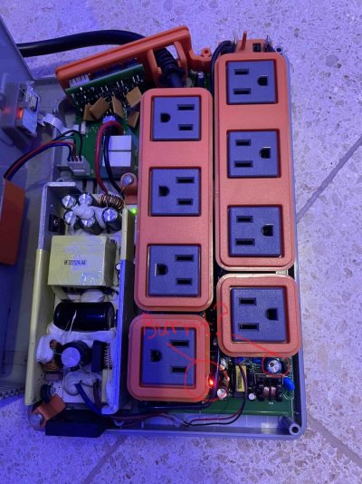
This is what I see. @Rimsky I circled things that did not look right.
Navigation
Install the app
How to install the app on iOS
Follow along with the video below to see how to install our site as a web app on your home screen.
Note: This feature may not be available in some browsers.
More options
You are using an out of date browser. It may not display this or other websites correctly.
You should upgrade or use an alternative browser.
You should upgrade or use an alternative browser.
Repairing EB832 AquaBus Power Issues or Why Head Unit Reboots Again


- Joined
- Jul 24, 2016
- Messages
- 238
- Reaction score
- 71
Hi @DrZoidburg.
the burned plastic was caused by myself with my soldering iron. My bad.
the black marking on the capacitor came like that. It seems just like a marking made with a permanent marker. Both new PSUs that I ordered came with that marking. I’m getting 12v dc out of the PSU. Can it still be bad? Is there a way I can test it other than the 12v dc output pins?
thanks a lot!
OP
OP
- Joined
- Oct 3, 2019
- Messages
- 679
- Reaction score
- 694
If the 12v PSU can't power the relays, its red LED usually flickers or goes dark when under load. Since you completely replaced the PSU, which is not my recommended approach, I'd make sure that the voltage it produces is actually 12v and not 5v.

- Joined
- Jul 24, 2016
- Messages
- 238
- Reaction score
- 71
Dear @_AV, the led on the 12v PSU is solid red and my multimeter reads 12v DC on the output pins. When I change the status of any outlet via Apex Fusion, the status lights on EB832 change, but there is no relay sound at all, not even a subtle sound. I will check everything again today, but really don't know what else to look for.
OP
OP
- Joined
- Oct 3, 2019
- Messages
- 679
- Reaction score
- 694
Have you tested the 24v outlets yet?
Also, the 12v PSU provides power to each relay to toggle it when the controller tells it to. With the outlet in ON state in fusion, trace the 12v power from the PSU all the way to the relay coil pin and make sure it's actually there. Which is unlikely. In which case, find out how far it goes from the PSU and why it stops where it does.
Also, the 12v PSU provides power to each relay to toggle it when the controller tells it to. With the outlet in ON state in fusion, trace the 12v power from the PSU all the way to the relay coil pin and make sure it's actually there. Which is unlikely. In which case, find out how far it goes from the PSU and why it stops where it does.
- Joined
- Jul 24, 2016
- Messages
- 238
- Reaction score
- 71
I did some investigation with my limited skills. The 1Link 24VDC outlets work. The relays click and there is 24V DC.
The 120VAC outlets still don't work. I can measure 12V on some of the relay pins, well, actually 11.26 VDC, not 12V. On those pins I can measure 11.24 VDC all the time, regardless of the outlet ON/OFF status.
The fan does not move. I'm not getting any voltage there.
The 120VAC outlets still don't work. I can measure 12V on some of the relay pins, well, actually 11.26 VDC, not 12V. On those pins I can measure 11.24 VDC all the time, regardless of the outlet ON/OFF status.
The fan does not move. I'm not getting any voltage there.

Have you checked under side of the board one video mentions some of the resistors burning out in other cases. Similar to yours with fan not working his was power supply also. Good idea to check triacs under the outlets if it is like older classic models. Could unplug the fan from pins and test pins with meter to rule out broken fan.
OP
OP
- Joined
- Oct 3, 2019
- Messages
- 679
- Reaction score
- 694
Just making sure you tested the aux 24v outlets, those with only 2 pins and not 4. 1Link outlets with 4 pins always have 24v power ON. While the two pin outlets are controlled by the relays and it's important to make sure those actually turn on and off.I did some investigation with my limited skills. The 1Link 24VDC outlets work. The relays click and there is 24V DC.
The 120VAC outlets still don't work. I can measure 12V on some of the relay pins, well, actually 11.26 VDC, not 12V. On those pins I can measure 11.24 VDC all the time, regardless of the outlet ON/OFF status.
The fan does not move. I'm not getting any voltage there.
For the 120VAC relays, you should be able to measure 12v DC voltage (or close to it) across the two pins like so:
And only when the outlet is in the ON state. There shouldn't be 12v DC across those two pins if the outlet is in the OFF state.
Don't worry about the fan. It won't turn on unless triggered by the temperature sensor.
Last edited:
- Joined
- Jul 24, 2016
- Messages
- 238
- Reaction score
- 71
Hi.Just making sure you tested the aux 24v outlets, those with only 2 pins and not 4. 1Link outlets with 4 pins always have 24v power ON. While the two pin outlets are controlled by the relays and it's important to make sure those actually turn on and off.
For the 120VAC relays, you should be able to measure 12v DC voltage (or close to it) across the two pins like so:

And only when the outlet is in the ON state. There shouldn't be 12v DC across those two pins if the outlet is in the OFF state.
Don't worry about the fan. It won't turn on unless triggered by the temperature sensor.
Yes, I tested the 1Link 24V (2 pin) outlets and both work. The relay clicks and they have 24V DC when ON and no voltage when OFF.
I'm starting to give up. I already damaged the fan thinking it was 12V, connected it to the 12V output and burned it. Starting to get desperate and more stupid.

OP
OP
- Joined
- Oct 3, 2019
- Messages
- 679
- Reaction score
- 694
The fact that you are getting the 24v ports working rules out connectivity and controller issues. This is good.Hi.
Yes, I tested the 1Link 24V (2 pin) outlets and both work. The relay clicks and they have 24V DC when ON and no voltage when OFF.
I'm starting to give up. I already damaged the fan thinking it was 12V, connected it to the 12V output and burned it. Starting to get desperate and more stupid.
Focus on 12v power from the PSU to the 120VAC relays.
OP
OP
- Joined
- Oct 3, 2019
- Messages
- 679
- Reaction score
- 694
No need to test, it has a hole in it, it's gone.Hi. Inspecting the back side of the board, I see that this chip looks a little burned. What is it? How can I test it?

This is a voltage regulator. It makes 3.3v from the input 12v.

- Joined
- Jul 24, 2016
- Messages
- 238
- Reaction score
- 71
I’m limited on what I can get locally. Do you think one like this would work?No need to test, it has a hole in it, it's gone.
This is a voltage regulator. It makes 3.3v from the input 12v.
Transistor Regulador de voltaje AMS117- 3.3 SMD
Regulador de voltaje de caida baja de 80 mA. La serie AMS1117 de reguladores de voltaje ajustables y fijos están diseñados para proporcionar una corriente de salida de 800 mA y para operar hasta 1V de entrada a salida diferencial.
I really appreciate all your help!
OP
OP
- Joined
- Oct 3, 2019
- Messages
- 679
- Reaction score
- 694
It is similar. You'd be running closer to it's maximum rated input voltage, but it's still within what I'd call normal. The original had V_in max at 20V, this one can't handle more than 15V. Your input voltage is 12v and may fluctuate up or down a bit. If that's all you can get, go for it.I’m limited on what I can get locally. Do you think one like this would work?
Transistor Regulador de voltaje AMS117- 3.3 SMD
Regulador de voltaje de caida baja de 80 mA. La serie AMS1117 de reguladores de voltaje ajustables y fijos están diseñados para proporcionar una corriente de salida de 800 mA y para operar hasta 1V de entrada a salida diferencial.www.electronicapty.com
I really appreciate all your help!

OP
OP
- Joined
- Oct 3, 2019
- Messages
- 679
- Reaction score
- 694
I now understand why. Too busy with all the acquisitions.Am surprised this hasn’t gotten taken down yet lol
- Joined
- Sep 7, 2019
- Messages
- 1,220
- Reaction score
- 1,157
No I think this thread is great it gives a lot of ppl good information. I think I seen you do a right up about this awhile go here or the Neptune page and it got taken down and I was disappointed. I like too see we’re there is flaws and we’re things could get better so the manufacturer can hopefully deal with the problemsI now understand why. Too busy with all the acquisitions.
- Joined
- Jul 24, 2016
- Messages
- 238
- Reaction score
- 71
I have a good feeling this is going to be it. One of the legs has conductivity to the 12V source and another leg has conductivity to a component near the relays and from there to the relays. All of them. I will try to get the part tomorrow and see. Already took the bad part out.It is similar. You'd be running closer to it's maximum rated input voltage, but it's still within what I'd call normal. The original had V_in max at 20V, this one can't handle more than 15V. Your input voltage is 12v and may fluctuate up or down a bit. If that's all you can get, go for it.

- Joined
- Jul 24, 2016
- Messages
- 238
- Reaction score
- 71
@_AV I'm unable to get specs for the original regulator. I just want to make sure that the pinout is the same as the new one I'm getting, since they are not exactly the same part. Do you think they will be pin-compatible? I want to avoid frying more things.
OP
OP
- Joined
- Oct 3, 2019
- Messages
- 679
- Reaction score
- 694
The pinout is the same. Just make sure you get it in the sot-223 package.@_AV I'm unable to get specs for the original regulator. I just want to make sure that the pinout is the same as the new one I'm getting, since they are not exactly the same part. Do you think they will be pin-compatible? I want to avoid frying more things.
Similar threads

- Replies
- 7
- Views
- 94


