

I'm getting started trying to build an all in one reef pi but also teaching myself a lot of this on the fly. I'm following the guide to build the power controller but the buck converter in the parts list (LM2596) leads to a 404 and all I can find are multipacks of that part. I found a buck converter of up to 21V to 5V on adafruit (MPM3610) and I'm wondering if I can use that as a simple substitution.
 www.adafruit.com
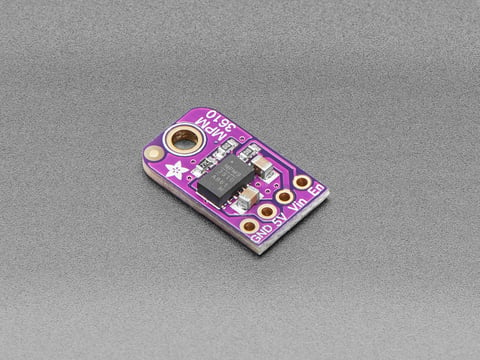
MPM3610 5V Buck Converter Breakout - 21V In 5V Out at 1.2A
This little buck converter based on the MPM3610 is a marvel, taking up to 21V input and providing a 5V output with up to 1.2A current. It's great for supplying power to popular 5V ...
www.adafruit.com