sarahgo

Community Member
View Badges
Joined
Nov 20, 2019
Messages
43
Reaction score
39
Location
Mission Viejo, CA
Rating - 0%
0   0   0
Hi everyone, I’m super stoked to finally be posting my 6 month long build thread this week. This is my first build thread, and it has lots of DYI, from building a light box for the main display, to conversion of a media cabinet for control purposes, and drilling my first tank. It’s been fun, and I hope to see your comments in the coming days after posting.

For now, please enjoy these teaser pics!
57EDFF9B-4A9A-43D3-A6BD-7FD983267226.jpeg
887C9EF9-6F00-4008-AB48-903C173A5F3A.jpeg
 
Last edited:
OP
OP
sarahgo

sarahgo

Community Member
View Badges
Joined
Nov 20, 2019
Messages
43
Reaction score
39
Location
Mission Viejo, CA
Rating - 0%
0   0   0
Main Display and Sump
Neptune Controller with Trident Water Analyzer, Energy Bar, Leak Detection Kit, and Flow Rate Monitor Kit.​
• 1 inch schedule 40 Formufit furniture grade blue PVC​
• 1 inch Schedule 40 PVC fittings for return, and drain pipes​
• X3, 1 inch spears ball valves​
• X4, ¾ inch spears ball valves for manifold​
• X2, ¾ inch spears compact ball valves for manifold in a tight space​
• X1, 1 inch IPEX true union three-way ball valve​

Display Refugium
• Formufit ¾ inch and ½ inch white furniture grade PVC for drains and return.​

Mixing Station
• X1, 1 inch bulkhead slip X slip​
• X1, ¾ inch spears ball valve​

Plumbing Schematics

1631772987043.png


Hi everyone, welcome to my first build thread where I will take you through my Innovative Marine 75EXT build journey. Keep in mind that some images below may appear out of order since this is indeed retrospectively posted. Lastly, although this is in retrospect, please feel free to post comments or suggestions. I am currently at the point in my build where I am considering my macroalgae for the display fuge. I am looking for nutrient export types, gorgonians, and sponges, and non-sexual types. I would greatly appreciate it!

A Little Background


This is my 5th reef tank in my time in the hobby. I have been reefing since 2011 and started with charity tank my grandmother received from a moving neighbor. The tank wasn’t in good condition after getting it home, but by then I was already so stoked I decided that I wanted an aquarium anyway. I trashed that one and just went out and bought a Marineland 55 gallon off the shelf at Pets Marts Since then, I have had a 10 gallon, a 12 gallon, a 100 gallon, my current 20 gallon, and now the 75EXT. Below are a few pics of tanks and critters over the years.


1631768766386.png
1631768777878.png

1631768837368.png
1631768847671.png
1631768859794.png

1631768887223.png
1631768899742.png


After selling everything off and relocating to SoCal About 2.5 years ago, I wanted desperately to build another tank, and ended up with my 20-gallon Red Sea Max Nano. After the purchase of our new house, I began planting the seed with my boyfriend last Christmas that I really missed having a larger tank. I promised him that I would break the 20 gallon down and condense them if he let me have a larger tank. He said, “but I like the 20 gallon. Can you just start another and keep the 20 gallon?” I had been given official permission to have TWO tanks! And so, began the journey of deciding what Aquarium manufacturer I would choose!

I needed a tank with a specific dimension to fit in the corner of our entertainment room next to our staircase. I thought it would be cool to have the overhead view of the tank from the landing and the upstairs hallway since our house is vaulted and open to the entertainment room below.
1631768979201.png

On my list of manufacturers was Waterbox Aquariums, CADE, and Innovative Marine. Although I have a Red Sea that I am happy with, the stand is a little wobbly when I’m cleaning the glass. I really liked the style of the stands from Waterbox, but the dimensions weren’t what I needed. I loved the CADE Aquariums and watched tons of videos on these, but I just didn’t like how the auto top off reservoir is integrated into the back of the display tank, which takes up real estate. After discussing with my boyfriend that CADE is not customizable on set-up, he said, “well you’re too type-A for that anyway; you’re going to want to change stuff, so you might as well start from scratch; Plus, those are really expensive!” I laughed inside because I knew I’d spend more if I built from scratch. I kept my mouth shut and agreed that starting from scratch was the way to go for me. This realization led me to Innovative Marine. With their EXT models (external overflow), I would gain extra display space while compromising on a smaller tank to fit my space. I went with the 75-gallon EXT and ordered the white APS stand to match my staircase.

I placed my order late December 2020, and received it on April 12, 2021. It was packaged very well in a wood and metal crate.

On first inspection, the tank was very nice looking. Upon closer inspection, I found two quality issues. One of the return drill holes was quite chipped, and there was a 5/8inch bubble in the silicon seam at the lower right wall of the tank in the back. The bubble was not necessarily in the structural seam, but rather in-between the side of the black acrylic baffle and the side glass.

1631769048704.png
1631769056102.png

1631769103553.png
1631769111046.png

I have never had a brand-new tank come to me like this before, nor have I seen tanks in store with bubbles in the seams, so I reached out to IM to see if they might offer some guidance. The salesperson was pretty condescending to me about it, and replied with, “all our tanks are like this.” I replied that maybe I shouldn’t have gone with Innovative Marine if all their tanks come with chipped drill jobs and bubbles in the silicone. He scoffed at me! In the end, I came out with an extended warranty, which does me no good should the tank fail, after all, it only replaces my tank, not my floor or the thousands of dollars I spent on livestock. Ultimately, I decided that I was going to fill it anyway. Although IM didn’t offer to exchange it, I could have easily driven it to them for exchange as I am about 45 minutes south of their facility. This will be my last Innovative Marine tank, unfortunately.

I digress…

DESPITE THE QUALITY ISSUES, the tank looks pretty sessy. I think the stand is above average stability being made of aircraft aluminum, however, the aesthetic value is lacking. The door panels look cheap next to the nice powder coated metal and appear to be some kind of foam core. This was confirmed when I used tape on the inside of the door, and pulled off the surface of the foam core. I would have expected expanded PVC, plastic, or something with more body. It doesn’t look terrible, and no one will notice but me me anyway. Overall, I think it’ll do the job, and matches my theme better than other options. I would rather it be stronger than prettier! The stand did come with an expanded PVC buffer to go right under the tank glass, and the tank has a 3/8inch foam pad glued to the bottom of it. There was an extra piece of expanded PVC to go on the bottom of the inside of the cabinet, but this was perplexing to me as it does not have enough structural integrity to hold anything on top of it between the two metal brackets that make up the bottom of the stand. More metal brackets on the bottom would fix this, but of course, this is in Innovative Marines court. It also came with a black shelf insert, which I chose not to use. I opted for more room rather than a shelf. I would have used if for the bottom of the stand, but the dimensions were not quite right.

The stand took about 40 minutes to put together, and I didn’t have problems squaring it like I had read on other
1631769186873.png

threads. You just need to be diligent in making sure the ends line up well before tightening the pressure locks. It also helps to not over tighten until the end. Once its altogether, put some weight on it like books or something and tighten everything down better. One thing I would have done differently is reverse the door on the wall side to open toward the front for easier access, even though that door won’t open functionally due to its position up against the wall. I will be accessing the tank from the right side and front only, due to its location. I used a furniture dolly to bring the tank in, and had my boyfriend help it onto the stand. Looks good where I planned it!

Once I got the stand in place, I began work on the bottom support. The stand only comes with two cross beams for support, and this makes leveling anything inside the tank impossible especially with the flimsy expanded PVC meant for flooring. The PCV board is also black as is the shelving that shipped with it. I decided against the shelf for more space. To replace the factory flooring, I picked up a white melamine coated plywood board from HD because it was cheaper than marine plastic, easy to clean, and matches the white theme. I cut it to size and painted the raw edges with 4 coats of high gloss latex paint. I also added more scaffolding for the board to sit flat. Without the additional support, the sump wouldn’t sit square on the bottom because of the gaps between the two metal supports. I repurposed an old plastic garden trellis into extra support, and glued them in place with gorilla construction adhesive.

1631769356159.png


I opted to make the melamine board removable in case of overflow emergency. This way I can quickly disconnect the sump, pull it out, and pull up the board for floor access. I fashioned a finger pull from scrap vinyl and stapled it to the board for easier removal.
1631769592237.png
1631769598857.png

After this was done, I wanted a way to waterproof the inside of the stand, not for catastrophic overflow, but for the minor spills that can occur with regular maintenance. This would also help to account for the small gaps between the metal frame and the melamine board since water can flow down between these gaps. For this, I bought a clear plastic shelf liner from Lowes. I cut it about 2 inches larger than the ID of the cabinet and folded the corners up to make a waterproof tray. It fit perfectly.

1631769771106.png
1631769777214.png
1631769782944.png

1631769802990.png


Sump and Plumbing


The tank was designed with a three-drain system located in an external overflow box behind the tank. IM makes an internal overflow, but I wanted the extra display space, and didn’t mind having the tank sit away from the wall to accommodate the overflow. I kept the three-drain system in mind when considering sumps. I’ve found the most popular choice among other build treads for the 75 was the Fiji Cube. I decided against it because I didn’t like the lip designed into the bottom of the sump. I imagined myself needing to remove the sump and accidentally chipping this lip causing a leak. I also considered the CWT Aquatics algae scrubber combo for two reasons: 1. I have never kept a refugium, and 2. I wasn’t sure how effective a small refugium would be in another cube style sump, and 3. I’ve heard that scrubbers are extremely effective. I didn’t like the reviews I was reading, so I kept looking. Lastly, I was considered the Trigger Platinum Cube. I have always wanted a trigger sump because they are super sweet looking, but I also was interested in the prospect of no more filter socks!! Fleece rollers are the new jam, so I chose this one. Although this sump was lacking a third drain outlet for my emergency, a quick search on their website revealed auxiliary 1 inch drain assemblies for purchase. I ordered my Platinum Trigger Sump and an extra 1-inch drain assembly. The sump fits perfectly inside the dimension of the stand. If you want more room around the sump, order a different model, because it literally fills the footprint to the edge from front to back.

I would have liked a larger refugium section for in-sump reactors to save space, but I didn't want a sump that filled the entire inside of the cabinet. At this point in my build, I was planning on having all of my gear inside the tank stand. I mulled over the idea for a bit, and ultimately decided I would create a control cabinet for my gear to save more space under the tank if needed. However, I still wanted space for RO top off, so the cube was the perfect size.

Lastly, because of the limited space within the refugium section of the sump, began kicking around the idea of plumbing in a display refugium (ultimately did this, so keep reading =). I was happy with the selection of space saving reactors on the market, so I have some options anyway. I also would have liked more baffles for better bubble trap and water level control in protein skimmer section, but this is really semantics. The only double baffle in this sump exists as a bubble trap between the refugium section and the return section.

For the bottom of the sump, I bought a standard anti-slip shelf liner to adhere for noise absorption, and I secured it with ATG tape.
1631770230764.png
1631770237193.png

I placed the sump in the stand and decided that I would position it with the fleece roll to the back, and the refugium to the front, and it would go in the left corner of the tank stand. This allows me to access the sump from the front doors, and access other equipment from the right door if needed. This configuration also placed the drains to the back and center of the tank stand for easier, more streamlined plumbing. This configuration also minimized the drain bends and curves to the sump, practically orienting them straight down. It’s a bit of a pain to change the fleece roller, but it’s a job made easier by removing the skimmer cup.

1631770371224.png
1631770381449.png

I decided to add my emergency drain opposite of the return plumbing. It seemed an easier retrofit since it is in the back with the other drains. I used a thread die to cut holes in the sump for the screws that came with the extra drain assembly purchased from Trigger Systems website. You can see the addition the best in the middle of the top down pic on the above right picture. I used a 1.25 to 1 inch barb reducer from the return pump to the vinyl tubing, since the Varios 8 return pump only has 1.25 fittings.

I had some trouble with the very short distance between the barbed fittings on the top of the pump, to the bottom of the hard plumb assembly. The distance was so short I couldn’t get the tubing to bend enough to make the connection. I didn’t want to go with silicone because I didn’t want to create the conditions for a blow-out. I have read a few cases where silicone tubing had burst on a return line. I ended up applying heat from a heat gun to gently bend the tubing into a slight “S” curve to get it to work correctly. After about 20 minutes of heat and manipulation, I ended up with the perfect form to go from my pump to the hard plumbing without obvious stress on the fittings and sump edges where the fittings screw into. Even better, the shape is now permanent. You can see the "S" shape in the pic on the left above. I added a union to the pump so I could remove for cleaning when needed.

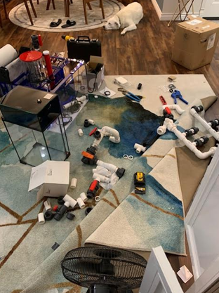
Right, so plumbing mock-up was set to begin, however, I literally spent most of a one-month period where I just stared; sat in front of the tank with the stand open. I wanted to think through every possible scenario and every possible piece of equipment that I might add in the future before cutting anything. I am a visual person, and it’s hard for me to make plans on paper, so I just went to HD and got PVC and fittings, only the must haves like 90’s and 45’s, (anything more fancy could be visualized in place during mockup), and began my plumbing journey. I had already purchased blue PVC that I would later replace the regular PVC once the mock-up was complete. I felt no reason to replace the fittings with the gray schedule 80 from bulk reef supply, because the white did the job fine. More importantly, white matched the overall color scheme of the tank, equipment, and room.
During this interim planning stall, I decided to paint the walls around the tank with a glossier sheen of the same color for water protection. I figured this might save my walls from salt creep and make it easier wipe off. I extended the sheen 2 feet larger than the tank dimensions in all directions for maximum protection. I also used clear silicone to seal the crack between the baseboards and the wood floor.

Before I started, first two things I decided on: 1. I didn’t want anything unnecessary that could cause flow failure in my plumbing. This meant no check valves. Instead, I opted for drilled holes in the lock-line on the tank side of the return. I bent up the lines to put the drill holes at the apex of the bend, then pointed the end back down into the tank and under the waterline. This would allow the holes to be exposed to air for proper siphon break before the end of the flair nozzle. 2. I modified my returns to accommodate 1inch PVC. Even though the tank had already been drilled for ¾ inch returns, I felt the reduction right at the tank might still improve flow through my manifold. Plus, that reducing factor might create a built-in back pressure for said manifold. I don’t know how much of this actually holds up to fact, but it seemed logical! For the rest of the pluming, I played around with a few designs, and first mocked up was done with no valves or manifold, just so I could visualize what the overall design would be. This worked out much better for me than drawing it on paper, and wasting my expensive colored PVC. I would be interested to know what other’s processes are, so feel free to comment below on that. Anyway, I knew I wanted a manifold, but I’d never built one. I didn’t like the designs I was seeing on other build threads, and although they were functional, they just didn’t work for my space. My solution was to utilize the vertical space in the upper interior of the cabinet. This would give me more real estate for design while keeping plumbing out of the way of added future equipment. This later enabled me to scaffold the plumping on the roof of the stand which allowed for a heftier design. I incorporated 90-degree fittings into my design, but I am not concerned with flow rate. I selected a return pump that should be able to handle this, plus I watched that BRS video on flow and plumbing where they concluded 90’s don’t make much of an impact. That was good enough for me.

Below are a few progression photos of how the mock-up developed and ultimately led to the completed design. You may also refer to the very crude schematic included at the beginning of the thread. I also decided not to include the Neptune flow rate monitor I had purchased on the return. The thought of it somehow causing an overflow was too intense. I kept flow modules for manifold equipment control in the future.

1631771082406.png
1631771089113.png

1631771096359.png
1631771102558.png

1631771110260.png
1631770848934.png

As the design was taking shape, I came to a design that would incorporate a two-sided manifold with reducers to ¾ inch ball valves. One side of the manifold flanks the right of the main return line, and the second side flanks to the left. I used two compact ball valves on the right section since this side is limited on space due to the orientation of the sump, and the proximity to other plumbing (the drain lines). I plan to have the right side for maybe a U.V sterilizer or for outlet for a display fuge. The left side of the manifold is for other reactors, maybe carbon, calcium, alae reactor, etc. I don’t really know right now what exactly I want. I will let the tank tell me in time what it needs. Separating the two sides of the manifold at the top of the main return is a true three-way ball valve. I wanted a way to be able to keep the return pump going while service one side of the manifold or the other for minimal down time. A two way wouldn’t have done the job, because it only diverts flow to the left or the right, but not in both directions simultaneously. I still put a spears ball valve at the bottom for redundancy on flow restriction if the adjustable controller on my pump ever breaks. I also made sure all ball valves were accessible from either under or on the right side of the tank since my tank sits quite close to the walls on these sides, and only fully accessible from right and front. If you notice in the back on the finished pluming, I realized this was necessary and moved the ball valves on the returns to the lowest point possible. The left one is accessible under the tank from the front, and the right one is accessible from the right side of the tank. Lastly, I designed it with PLENTY of unions so my sump, and every run of PVC can be taken out quickly if needed. Overall, I am very pleased with the pluming job, although It gave me many gray hairs.


FINISHED MOCK-UP PLUMBING:


1631771253577.png
1631771272324.png

1631771301632.png


Completed Design:

return plumbing.jpg

equip.jpg

Leak test was successful…well, I say successful =). I forgot to glue one joint on the return, and I also missed a pesky rubber gasket on one of the unions. Nothing like your heart jumping into your throat at the site of water quickly leaking out of the plumbing! Here are a few photos of the leak test progression:

leak 1.jpg
leak 2.jpg

IMG_9040.jpg


Shout out to Irvine Pipe and Supply in Southern California. They usually don’t sell to the public, but they agreed to sell to me since spears valves are not sold in retail stores nearby.

Valve breakdown: I utilized the ¾ inch true union ball valves for the left side of my manifold, two 3/4 compact ball valves on the right. Three 1-inch true union ball valves located at the initial pump output, and the two flanking returns. One 1-inch spears gate valve for secondary drain tuning. Lastly, I used a true union three-way ball valve at the manifold split for optional shut off to either side for maintenance.

The next section, DIY LIGHTBOX will be posted latest this weekend! Thanks for checking it out so far!
 
Last edited:
OP
OP
sarahgo

sarahgo

Community Member
View Badges
Joined
Nov 20, 2019
Messages
43
Reaction score
39
Location
Mission Viejo, CA
Rating - 0%
0   0   0

DIY Light Box for Two Radion XR30Pro


First off, I am not a fan of the prospect of shadowing in my tank. Secondly, I am not sure at this point whether this tank will be SPS dominated, LPS, or mix. I have never had an SPS dominated tank before, and I would like to make a contingency plan to allow my system and lighting to accommodate whatever I decide for the future. After ordering two XR15 and placing them over the tank, then exchanging those for one XR30, I ultimately decided to order one more XR30. I was having a hard time with the recommended spread, both from recommendations on Radion website, but also considering the BRS video on optimal light placement regarding light type/dimension. The Nuvo 75EXT dimensions are about 36X24, a weird mix between square and rectangle. Two XR15's don't cover the recommended spread from front to back, and one XR30 doesn't cover the long way. I mean, you could totally get away with one, but with my rock work, one created too many shadows at the far ends of the tank, IMO.

I really wanted a “floating” appearance above the tank, but more importantly, I wanted to minimize light spill into my entertainment room where we listen to records on a regular basis. I had ordered the mounting bracket for the lights, and just didn't like the bulky appearance in this corner of the room. I wanted something a little more elegant. Since prebuilt mounts weren't working with my theme, I opted to build something. I had in the past built one for my 100 gallon (above in my past tanks and critters entry photos) which turned out well, so I knew I could do it again! The configuration would be as pictured from TOP DOWN:

1631980823660.png


I visited Home Depot and picked up some finished poplar boards. At almost 8 inches wide by about 1 inch thick, I felt this would be aesthetically substantial enough to look somewhat professionally made. Furthermore, to prevent light spill, I concluded the box dimensions should be deep enough where the lights can sit up inside the box and above that tank at the recommended 8 inches above water. Lastly, the OD of the box would need to be smaller than the perimeter of the tank. If you choose to create a hood style light box, where the wood meets the glass, you don’t have to decrease the size of the box. However, for a floating configuration it seems to matter. For the finished size, If you can see the light peaking between the water line and the underside of the box, you will have light spill. If you can see the light only while looking up and through the water, then light spill should be non-existent. I decided on a dimension that would be 3 inches smaller than the tank when centered above it, so basically, I measured the tank minus 6 inches, and this was the size of my box. I needed a bracket to mount the lights to, and for this I used an aluminum “L” bar from the metals section of Home Depot.

alluminum.jpg

poplar.jpg


I chose aluminum because it is easy to cut with a hack saw, but I knew I would have to paint it to prevent corrosion over time. I cut the box to size and used deck screws to hold it together. Since I don’t have a miter saw, I just cut at a 90 degree. I cut them in a way where the front of the box would be seamless from the front view. This hides the seam from the front perspective, and creates a more finished look.

IMG_9187.jpg


I finished the screw holes with counter sink bits and wood filler for a smooth look once painted.

IMG_9204.jpg


It was also helpful to use clamps to align the pieces, followed by predrill, countersink, and then screw it together. To mount the metal L brackets to the inside of the box, I used a zinc coated corner bracket. I drilled holes in the aluminum to fasten the lights to the bracket, and to fix the brackets to the inside of the box. For fixing to the box, I used a simple, two-hole corner bracket.

IMG_9198.jpg
IMG_9208 (1).jpg

So I didn’t have to mess around with measuring where my lights would be, I drilled three sets for each light for spacing options after it’s installed over the tank. I messed up on a few of the holes, but at this point in the build, I didn’t feel like replacing the bracket for aesthetic purposes.

IMG_9205.jpg
Angry He Man GIF


Another thing that didn't turn out the way I wanted was the smoothness of the boards. These were supposed to be finished poplar, but I noticed about halfway into the project that a couple of them were wavy, although sanded. I assume that the saw got a little choppy while they were being cut. I didn't really want to bother with going back to the store to buy more, so I just picked the best sides, (front an back were wavy), and faced the worse sides to the inside of the box. I did a dry fit of the lights prior to painting:

IMG_9203.jpg


I decided to use the outer most holes for two purposes. This spacing feels wide, but it was in line with the BRS video on par and light placement, but I also wanted the lights to be as close to the inside of the box a possible to further prevent light spill. I primed the box with KILZ weather proofing latex primer and painted it with white gloss latex paint to match the trim on my staircase; it is the same paint. I used Behr matte black spray paint on the inside of the box because I wanted it to minimize light reflection in the room. The brackets were painted with a high gloss Rustoleum spray paint. I used steel brackets to reinforce the joints in each corner (pictured above). When finished, I did a dry fit over the tank to make sure everything looked good. I particularly liked the contrast of the matte black and the gloss black. Fresh.

IMG_9220.jpg

IMG_9223.jpg

Finished box, scaffolded above the tank:

IMG_9228.jpg
Untitled.jpg


To mount the light box, I use two TV mounts to achieve the "floating" look. In retrospect, it would have been fine with just one centered for three reasons: 1. the mounts turned out to be pretty robust, and 2. I found out that I have a stud pretty much dead centered behind the tank, and the other was offset to the left, and 3. I ended up scaffolding the box to the wall anyway for extra piece of mind. In the end due to the placement of the studs, the mounts are offset when viewed from the front of the tank, but this doesn't bother me too much. To scaffold the box, since TV mounts are made largely for vertical load, not horizontal, I utilized small gauged galvanized wire from HD. I used four eye hooks; two in each inside corner of the front pane, and two to connect the wire to the wall from the box. to secure the wire to the eye hooks, I used crimping sleeves, and to secure the eye hooks into the wall, I used a bit of silicone (since this is not load bearing and the mounts do 90% of the work). lastly, you can see this offset if you are in front of the tank, but this doesn’t bother me. I may eventually paint the mount on the wall side white to camouflage it. To me, it looks pretty darn good anyway, so there.

IMG_0042 (1).jpg

IMG_0046.jpg
IMG_0043.jpg
IMG_0047.jpg

C7665637-2986-4A54-9902-04C23C836C46.jpg
AFFA2347-1962-4B4D-A79D-E8E36F678237.jpg


Let me know what you think!

Thanks for sticking with my build! Stay tuned for the next section which will cover my rock scape!
 
Last edited:

rioreef

Active Member
View Badges
Joined
Feb 24, 2015
Messages
159
Reaction score
122
Location
VA
Rating - 0%
0   0   0
Great initial write up. How about some updates?
 

Fusion in reefing: How do you feel about grafted corals?

  • I strongly prefer grafted corals and I seek them out to put in my tank.

    Votes: 1 7.7%
  • I find grafted corals appealing and would be open to having them in my tank.

    Votes: 11 84.6%
  • I am indifferent about grafted corals and am not enthusiastic about having them in my tank.

    Votes: 1 7.7%
  • I have reservations about grafted corals and would generally avoid having them in my tank.

    Votes: 0 0.0%
  • I have a negative perception and would avoid having grafted corals in my tank.

    Votes: 0 0.0%
Back
Top