Starting over - IM 20 NUVO Fusion Pro Build

Jason Scalise

Active Member
View Badges
Joined
Apr 13, 2019
Messages
280
Reaction score
250
Location
Phoenix, AZ
Rating - 0%
0   0   0
(reposted in the proper location...error first time.)

New Build Thread - IM 20 NUVO Fusion Pro

Hello. After a recent catastrophic structural failure of a much larger tank and losing everything (RedSea 425XL)...and thinking it would be a long time before I would devote time and effort into another build, I decided to go with a 20g IM NUVO Fusion Pro.

I am still planning on a much larger system at some point in the future. Dedicated equipment room, remote sump, etc. But that will be a bit in the future.

For now, I liked the price point, the included/bundled equipment, flexibility of the IM 20 Fusion Pro as it would allow me to tailor a few things. I like the clean look as well.

The plan is a SPS-weighted mixed reef. I have had good success with SPS in nanos and would like to continue that if possible.


Equipment List (for now)
Display Tank – IM 20 NUVO Fusion Pro
Stand – IM APS Aluminum stand

Return Pump – stock MightyJet 326 GPH
Heater – BRS 100W Titanium Heater Element (bundled with InkBird...but wont likely be using the IB and instead will control it through my Apex and temp probe).
Light – RedSea ReefLED 90

Apex control unit with 1Link, FMM x 2, Salinity Probe, pH probe.
AWC – Neptune DOS
ATO – Gravity fed from RO freshwater reservoir with multiple fail safes. (I will describe this in more detail separately)

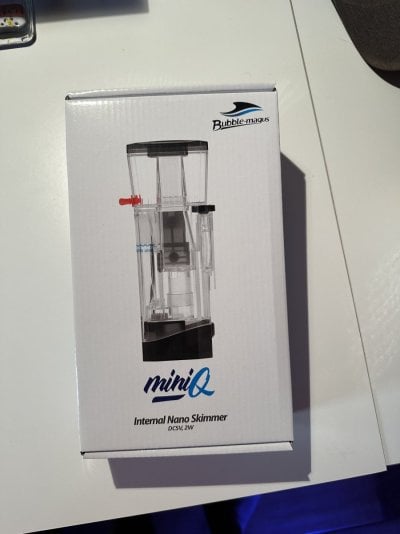
Skimmer (not installed yet...too early) - Bubble Magus MiniQ Nano
Dosing (not needed yet, of course) - Neptune DOS

Salt – Tropic Marine
Caribsea Bahama sand and about 15lbs live rock from LFS.

Saltwater mixing station is in the garage and all water lines feed through wall and into tank and waste drains. The 2 reservoirs (fresh and salt) are 65g each...and yes I know that is 6 times more volume than the entire DT....but that is leftover from my 112g tank and, it is set up to be fully automated.

I will skip the parts of the unboxing as others have described that well.
This is what happens in this house when you unbox...almost instantaneously.
IMG_0775.JPG


more to come.
 
OP
OP
J

Jason Scalise

Active Member
View Badges
Joined
Apr 13, 2019
Messages
280
Reaction score
250
Location
Phoenix, AZ
Rating - 0%
0   0   0
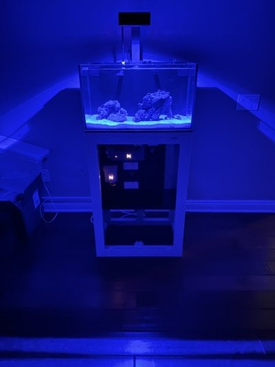
The aluminum APS stand arrived and it went together fairly quickly. Seems very sturdy and it came with the shelf unit. (BTW...no metal shavings in the box or on the floor like some people described so perhaps they addressed that at the IM factory).

Plenty of space for a 20g within the stand. I do wish there was an option to easily remove the side panels for access. Had I a bit more time I probably would have worked on a way to do so and ‘pop’ them (or some replacement panel) in and out. That would be nice...but maybe in the future.

set up and stand.png


I like the minimalistic look so I wont plan on having anything in the stand other than the controller units for Apex, pump, etc.
 

V A R I A N T

Active Member
View Badges
Joined
Oct 18, 2021
Messages
424
Reaction score
492
Location
Washington
Rating - 0%
0   0   0
I had one of these for a couple years. Very nice tank. I upgraded the pump to the Deskjet 538 and it fits nicely. The only issue I had was that the glass scratches easily. My Nano Flipper put a 8” scratch in the front pane. I ran bare bottom so wasn’t a substrate issue. Good luck!
 
OP
OP
J

Jason Scalise

Active Member
View Badges
Joined
Apr 13, 2019
Messages
280
Reaction score
250
Location
Phoenix, AZ
Rating - 0%
0   0   0
First modifications

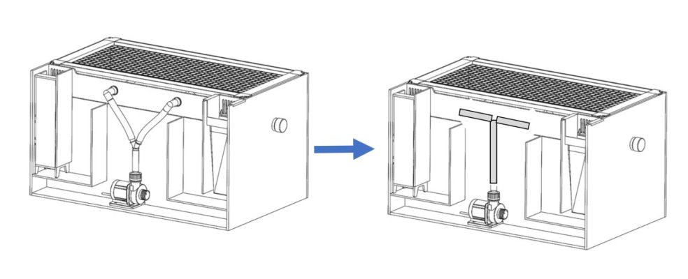
The way IM has the return pump tubing situated in the return chamber, consumes a fair amount of space in my opinion.

There is not much room in the front-to-back dimension in the return chamber given how far out the elbows in the return chamber stick out. It is not much but for tiny spaces, every bit helps. I want to install a float valve here for my ATO and desire the space. I decided to modify it a bit.

Screenshot 2022-12-30 at 8.45.22 AM.png


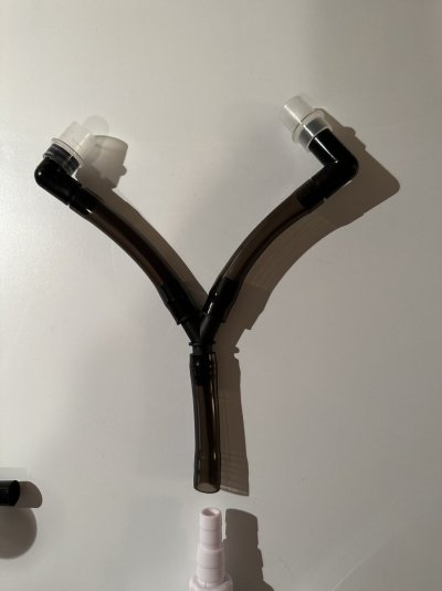
This is the stock configurate with the Y split going to each elbow.


IMG_0034.JPG

IMG_0038.JPG

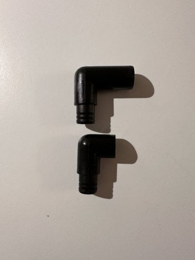
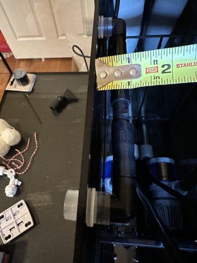
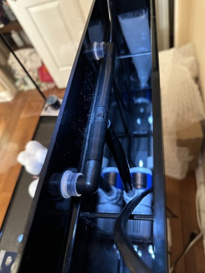
I cut down the elbow a bit (the part that connects to the flange that goes into the DT. (pre-cut on top, modified on the bottom).

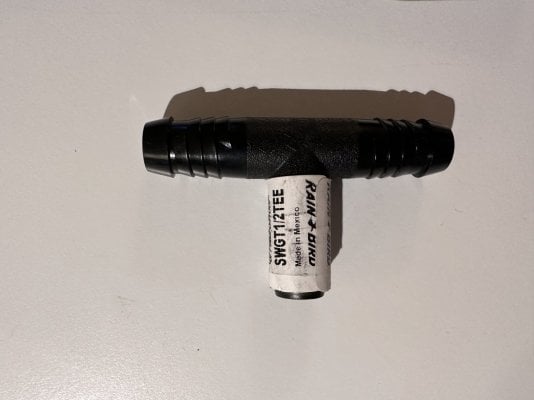
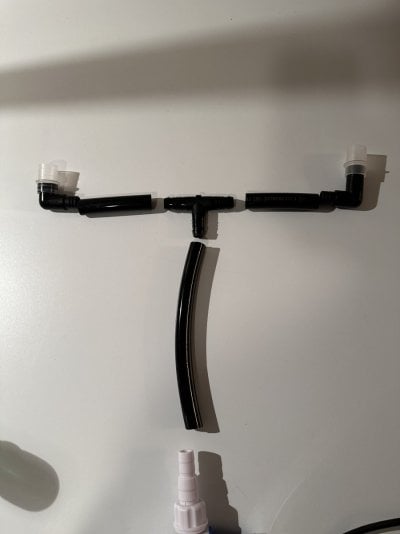
And I replaced the Y with a T to move that ‘bulk’ of the connection higher up in the chamber. That said, I probably would have done the job with just the modification of the elbows.

IMG_0035.JPG


IMG_0037.JPG


And now it looks closer to this.
return tubing mod.jpg
This created an extra 1 inch of clear clearance in a 3 inch space...33% pick up.
 
Last edited:
OP
OP
J

Jason Scalise

Active Member
View Badges
Joined
Apr 13, 2019
Messages
280
Reaction score
250
Location
Phoenix, AZ
Rating - 0%
0   0   0
I now have clearance for my float valve which I have connected to a 3D printed clamp along with a couple of optical sensors (Neptune) that I had left over from prior tank. More on this later when I have it all hooked up...but basically, if the float fails, the optical sensors will cause the water line to close.

IMG_0042.JPG

IMG_0041.JPG


when the ATO is set up, will show more pics. perhaps have some time today today to do it.
 
OP
OP
J

Jason Scalise

Active Member
View Badges
Joined
Apr 13, 2019
Messages
280
Reaction score
250
Location
Phoenix, AZ
Rating - 0%
0   0   0
Heater Placement

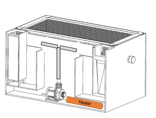
The BRS 100W heater is too long to fit in the baffle chamber sitting upright. Smaller heaters would fit fine there. I chose to put my titanium heater lying on the bottom of the main chamber. Basically right near the return pump.


Heater placement.jpg Fists fine there and uses what would otherwise be unused space. And saves room for the 2 baffle chambers for something else.

will be controlled with Apex and associated temp probe.
 
OP
OP
J

Jason Scalise

Active Member
View Badges
Joined
Apr 13, 2019
Messages
280
Reaction score
250
Location
Phoenix, AZ
Rating - 0%
0   0   0
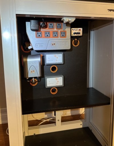
Now for the custom control board for all of the modules and keep things looking clean and organized.

I also wanted to be able to remove the board, add new modules and so on...without being locked down. One thing that I appreciated very quickly on prior builds is the need to be able to access the back and make adjustments without major efforts. A sealed off cabinet looks nice but is totally impractical, to me.

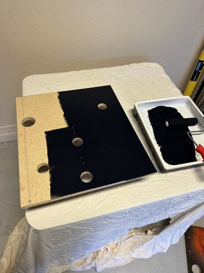
A sheet of 3/4 particle board from the hardware store. Cut down to size and drilled for cords for the various modules. I cant stand looking at nests of cords.
Painted the board with some flat black paint to complete the look.
This will attach to and sit on top of the shelf that came with the stand.
IMG_0058.JPG


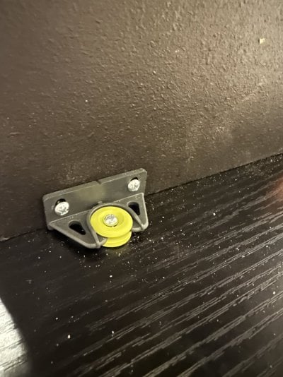
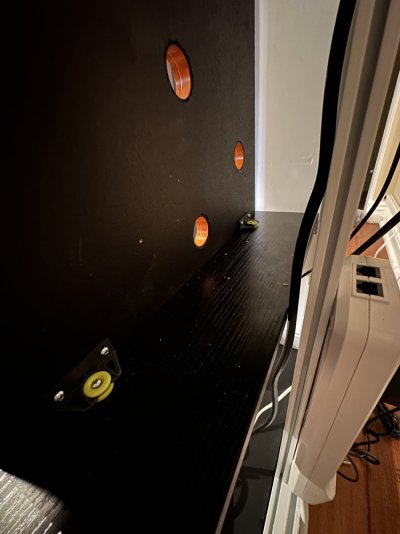
I found these nice brackets which allow the control board to be snapped in and out of place for easy maintenance and adjustments. this is on the back of the board.
IMG_0062.JPG IMG_0063.JPG


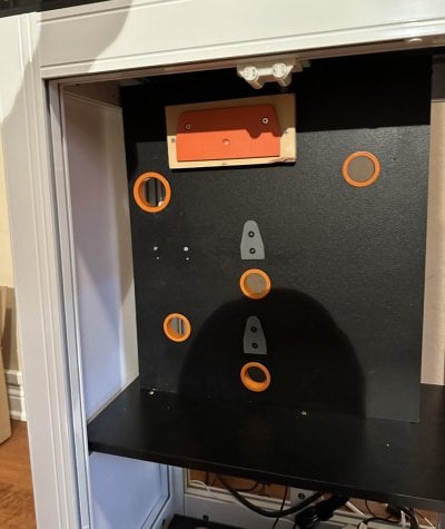
View from the front before and after the modules are placed on they holders.
IMG_0060.JPG IMG_0074.JPG


Leak test shortly....
 

V A R I A N T

Active Member
View Badges
Joined
Oct 18, 2021
Messages
424
Reaction score
492
Location
Washington
Rating - 0%
0   0   0
Did you find those brackets online or at a big box store? Can you share a link to them? Thanks!
 

wpapaslow

New Member
View Badges
Joined
Dec 27, 2022
Messages
19
Reaction score
20
Location
Bozeman
Rating - 0%
0   0   0
Heater Placement

The BRS 100W heater is too long to fit in the baffle chamber sitting upright. Smaller heaters would fit fine there. I chose to put my titanium heater lying on the bottom of the main chamber. Basically right near the return pump.


Heater placement.jpg Fists fine there and uses what would otherwise be unused space. And saves room for the 2 baffle chambers for something else.

will be controlled with Apex and associated temp probe.
Are you at all concerned with the lack of flow over the heater in that configuration? A thought... You could run a soft line from the pickup of your pump into the far corner of the "heating chamber." That would force water to be drawn from left to right over the heater and into the return pump. I've noticed in my nano those cubbies seem to be a good spot for stuff to collect. So it could also keep that from happening?
 
OP
OP
J

Jason Scalise

Active Member
View Badges
Joined
Apr 13, 2019
Messages
280
Reaction score
250
Location
Phoenix, AZ
Rating - 0%
0   0   0
Are you at all concerned with the lack of flow over the heater in that configuration? A thought... You could run a soft line from the pickup of your pump into the far corner of the "heating chamber." That would force water to be drawn from left to right over the heater and into the return pump. I've noticed in my nano those cubbies seem to be a good spot for stuff to collect. So it could also keep that from happening?
thanks and thought of that too.
I am not all that concerned, I guess.

Even if the water within the 'heater chamber' is much warmer while the heater is on, it will convect up and into the pump chamber where it will circulate and be captured by the pump's flow.

My temp probe is in the last chamber before water is subjected to the return pump and furthest way way from the heater, so to speak.

that said, your suggestion of a soft line from the intake would draw more flow across it if needed.
 
OP
OP
J

Jason Scalise

Active Member
View Badges
Joined
Apr 13, 2019
Messages
280
Reaction score
250
Location
Phoenix, AZ
Rating - 0%
0   0   0
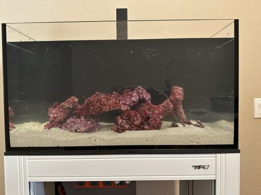
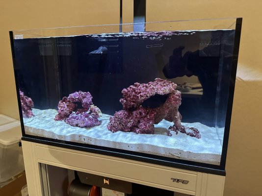
With major electronics and equipment now in place, time to do the leak check and start this thing cycling. With the leak check done, I am going with live rock and Caribsea Carribean live sand and Tropic Marine salt mix to 1.026 sg. Should not take long for cycling bacteria to set up. Adding some Microbacter that I have as well. I want to get this going while I work on other things like ATO.
IMG_0053.JPG

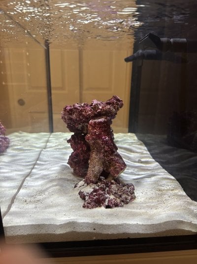
Basic aquascape for now. Just trying to get the biology going for now.

Light installed today. RedSea ReefLED 90. I installed it so I could get its powerbrick installed on the back of the control board and be done with that part. But wont be turning on the lights for now...until things are cycled and getting ready to add livestock. No hurry.

IMG_0070.JPG
IMG_0072.JPG
 
OP
OP
J

Jason Scalise

Active Member
View Badges
Joined
Apr 13, 2019
Messages
280
Reaction score
250
Location
Phoenix, AZ
Rating - 0%
0   0   0
This is my first RedSea LED fixture. It is very bright but it is only a 20g tank so I am sure that has something to do with it. I am confident this is the only light I will need for this set up. Shimmer effect is very prominent.

Although the app is easy to use, the only drawbacks thus far is that it seems to be kind of slow in making adjustments when using the app. In other words, when changing intensity or settings, it seems to take a few seconds for the app to communicate with the LED before the changes take hold. Kind of annoying. My previous experience with AI Primes was essentially an instantaneous response between app and light. Perhaps its me but will keep working on this part.
 
OP
OP
J

Jason Scalise

Active Member
View Badges
Joined
Apr 13, 2019
Messages
280
Reaction score
250
Location
Phoenix, AZ
Rating - 0%
0   0   0
Time to install/Build the ATO

So I wanted to take a bit of a different approach with my ATO setup.

(I fully recognize that the following approach will be considered “NOT necessary” by some, I don’t disagree...but it has some potential advantages in my mind).

Keep in mind that I already had set up a saltwater mixing station about 15 feet away in my garage from my previous system. I held on to that when my previous 425XL Reefer failed. More on the use of the mixing station later.

The goals that I wanted to accomplish were an ATO that:
  • 1) Had a low likelihood of failure
    • I am out of town a lot and want it as automated as possible
  • 2) A system with low likelihood of pump failure “on” leading to a flood or failure “off” leading to underfilling or going dry.
    • Lots of reports of pumps failing, needing to be replaced, etc. That is not unique to ATO pumps, of course. Most people don’t end up with a ATO-induced flood....but it can happen.
  • 3) If there is a failure like a ‘stuck in the on position’ pump...backup sensors that can cut the water flow off even if the pump itself is stuck on.
  • 4) Given that this is only a 20g system, avoid salinity swings with incremental ATO pump on/off cycle filling.
    • This is not a major issue as the salinity ‘swings’ would be minor and likely not that noticeable or biologically significant. But if I can avoid it, even better as a small bonus.
  • 5) Ability to not have to manually refill reservoirs.
    • I don’t like being a bucket sherpa.
    • And with my travel, I never want to worry about it running too low. Therefore, would need a larger reservoir just in case....which brings me to my last point below.
  • 6) Avoid a RO ATO reservoir in my stand or sitting next to it.
    • I know this is a common solution and it works well for many. I just don’t like the way it looks. Plus, its not just the reservoir but also the wires for sensors, pumps, etc.
    • I know, that is why they make cabinet doors...so you can close them...I know....but just saying.
So I decided to build a “hybrid gravity-fed solution” from a RO reservoir in the garage directly into the back of the AIO chamber with a float valve. But wait, hold on...let me explain.
 
OP
OP
J

Jason Scalise

Active Member
View Badges
Joined
Apr 13, 2019
Messages
280
Reaction score
250
Location
Phoenix, AZ
Rating - 0%
0   0   0
Hybrid ATO Build and Install

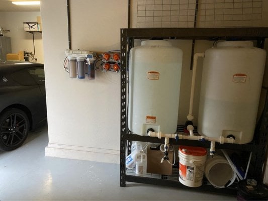
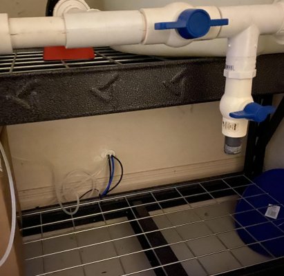
In the garage, I have two 65 gallon tanks: one for storing RODI water (left) and one for NSW (right).
Yes, I know that combined, these are about 6x my entire DT volume. I get it. Overkill for a 20g....but this was for my previous set up. In that set up, I ran 1/4” tubing directly to the sump with multiple optical water level sensors that triggered a motorized ball valve safety switch if in an overfill situation if the float valve were to ever fail. But in this case, I don’t have an under-the-DT sump, of course.

Screen Shot 2019-12-27 at 5.42.13 PM-2.jpg
Screen Shot 2019-12-27 at 5.51.25 PM.jpg

I would have replicated that but, it just so happens that the water level in my new 20g DT is basically at the same height as the 65g reservoir when 75% full. In other words, I could not use gravity to the DT because, in case you did not know.....water does not go uphill with gravity.

The fact that the two water levels in the tanks ended up at the same height was just an odd and unfortunate coincidence to my initial plan. And there was no way I was going to be able to easily raise the mixing station rack by 5+ feet to overcome that.


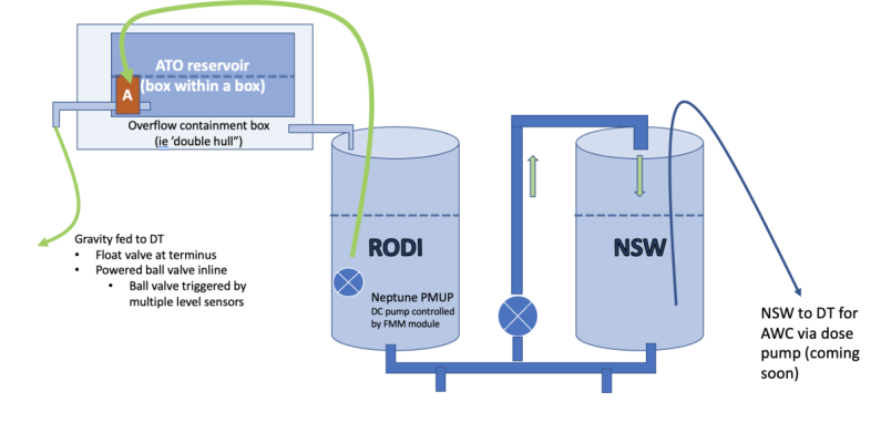
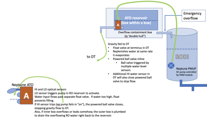
So, I decided the solution would be to intermittently pump a small amount of RO water into a new “double hull” reservoir placed on a shelf above the main 65g holding tank. Then have that feed by gravity into the back of the main tank as the ATO. Here is a schematic

Screenshot 2023-01-05 at 3.16.09 PM.png

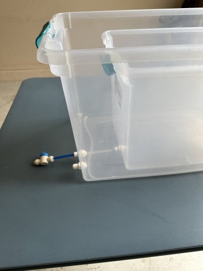
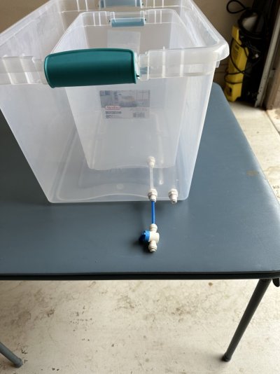
I bought two plastic storage containers at Home Depot. Each has a lid and the smaller (about 6g) can fit within the larger one (about 16g). The internal container holds the RO water and the outer container is the 'double hull' and acts as a safety in case of overflow of the inner container should the filling pump fail "on".
I then plumbed a gravity-fed drain from the internal container with these 1/4" push-lock bulkheads.
IMG_0085.JPG


The blue RO line will flow via gravity to the DT as the ATO.
The second bulkhead on the outer container that you see on the right is an emergency drain in case of inner reservoir overflow. and this will flow via gravity right back into the large 65g RO holding tank. This is the 'double hull' aspect. and I only need to fill the inner container to about 20-30% full thereby limiting the amount of RO that could ever flow into the DT and reduce the risk of major overfilling.
IMG_0086.JPG

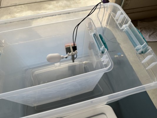
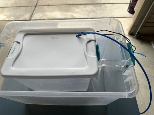
The optical sensors and float valve are placed in the inner container to automatically pump RO water into the ATO tank only as needed. This is all controlled by Apex controller and code.
IMG_0088.JPG
IMG_0089.JPG

The schematic now looks like this where the 'red box A' in this schematic is the optical sensor mount and float valve (neptune) inside the smaller container.
Screenshot 2023-01-05 at 3.34.23 PM.png


I can control how much RO water is in the reservoir by raising the placement of the sensors up or down.
I don’t need 6g for a long time away because the PMUP will keep replenishing it on a schedule, with auto shutoff if the pump is on too long, etc. I only need about 1-2 gallons in there at a time.
Keeps just enough water so that if every safety does fail one after another, there is only a small potential volume going to it (and my house)....not the entire 65g reservoir.

in the back of the DT, I have the RO line from the ATO goes into a small mechanical float valve (which is why I wanted as much room as possible in that chamber). I also have another pair of optical sensors there. Low sensor alerts if water is too low and HI sensor indicates overfilling.
(I will post a pic of that later....thought I had one handy but need a new one).

Video of ATO in back of DT


In the event of overfilling of the DT or overfilling of the ATO reservoir (on a separate HI optical sensor), it will trigger the activation a motorized ball valve. This is wired to the FMM unit of my Apex.
Screenshot 2023-01-05 at 3.41.06 PM.png
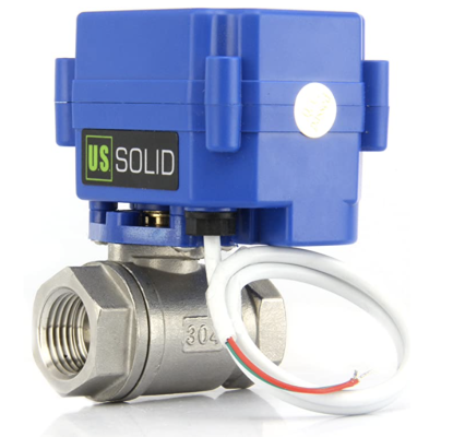
(Motorized Ball Valve- 1/4" Stainless Steel Ball Valve with Full Port, 9-24V AC/DC and 2 Wire Auto Return Setup by U.S. Solid. Bought from Amazon for about $30.)

I like it much better than the powered solenoid option because in order for most solenoids to stay open (which is what I want most of the time), they need to stay energized (powered). That draws power and they get warm, can fail, etc.
This powered ball valve, on the other hand, draws almost no power in either open or closed. It only draws power (pretty minimal) when closing or opening. For my application, it's perfect as it sits dormant 99% of the time unless called upon.
This closes the ATO line to the DT in any unusual circumstances. I coded the Apex to do so if the there is a PMUP error, overfilling of the ATO reservoir, overfilling of the DT, if the main tank return pump is off for more than 10 min, etc.


In summary, I now have a ATO that accomplishes all of my goals.
  • multiple redundancies.
  • ATO reservoir leak drains right back into the RO holding tank,
  • gravity fed for real time filling on evaporation demand.
  • No reservoir in sight of the DT and not taking up room.
  • pump failures accounted for.
  • very low risk of flooding or overfilling.
I was considering the double hull concept for a ATO reservoir next to the tank too but since I could put in the garage as well, that was even better.

So far so good. works perfectly.Video of ATO in back of DT
 
Last edited:
OP
OP
J

Jason Scalise

Active Member
View Badges
Joined
Apr 13, 2019
Messages
280
Reaction score
250
Location
Phoenix, AZ
Rating - 0%
0   0   0
Here is what the ATO in the back chamber of the AIO display tank looks like.
Screenshot 2023-01-06 at 6.17.54 PM.png

Click for video

  • RO line into float valve. Adjustable height on the mounted plastic rod.
  • Submerged low optical sensor in case water gets too low (cant see here)
  • HI optical sensor on a magnet mount in case water gets too high. This will trigger the motorized ball valve on the RO line to close.
 

Attachments

  • IMG_0109.MOV
    30.4 MB
Last edited:
OP
OP
J

Jason Scalise

Active Member
View Badges
Joined
Apr 13, 2019
Messages
280
Reaction score
250
Location
Phoenix, AZ
Rating - 0%
0   0   0
Skimmer

I decided to get the new skimmer going.
I purchased the MiniQ Nano Skimmer from Bubble Magus.

IMG_0111.JPG

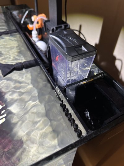
It fits very well in the either the left or right secondary chamber of the back. Actually, extra room left over.
Easy to install and easy to set up.

It has a built in drain in the collection cup (red button in the pic on the far side of the collection cup).
Nice little touch for such a small skimmer....can drain to a larger waster canister below somewhere and not have to worry (much) about an overflow event.

IMG_0113 2.JPG

Very quiet so far.
Still breaking in, of course.
I have some micro bubbles in the DT but it is just getting warmed up. I am sure it will calm down over the next couple days.
I am happy with this so far.

Here is a short clip of it operating.

getting there.....
 

TOP 10 Trending Threads

Back
Top