OP
OP
otherwise, yeah i'd choose it
Follow along with the video below to see how to install our site as a web app on your home screen.
Note: This feature may not be available in some browsers.


Great advice about extra capacity for siphoning!IMO, building your own sump is one of the most fun and educational things you can do in this hobby. It's SO much easier these days with the baffle kits that are now available. Many are designed for specific cheap, mass-market tanks that you can buy at any pet store, so they fit perfectly. One word of caution: make sure you have plenty of capacity for siphoned water when the power is shut off! Whatever overflow you're using will dump some amount of DT water into your sump when the return pump turns off until your drain siphon break level is hit. Speaking of which, make sure you have a siphon break on your return line!


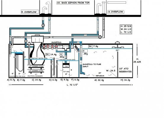
Thank you for the compliment on my diagram … I’ve been working on these plans for months…someone said ‘go slow’, so I am trying to think of everything and take my time to do this right!Great planning diagram! You put mine to shame! A few points/suggestions:
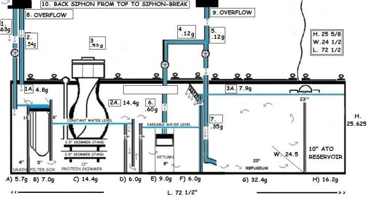
1) Draining volume: The reason he said it would depend on flow rate is because flow rate will affect water level in the DT. If your flow rate is above the max rate that the return plumbing can handle, the water level in the DT will be higher than if your flow rate was at or below the return plumbing max flow rate. Therefore, the volume of water draining into the sump after pump shutoff will be variable and directly related to your return pump flow rate. The optimal flow rate for my 300G Marineland tank is 600 gph according to the manufacturer. Originally, I matched my return pumps to that, but later jacked up the flow to get more turnover in my system. The water level in the DT went up and so did the power-off drain volume. I don't know how to predict the drain volume though. Maybe estimate max possible drain volume by measuring height from first siphon break to top rim of your DT and then multiply by width and length? That's probably overkill because you're not going to want to run your system with water level right at the tip top of your DT.
2) Filter sock section: is there a raised lip on the right side of the holder to keep water from flowing over the top into the skimmer section? I can't tell from the drawing. You want one, but not too high so that if the socks get clogged, you can still overflow into the skimmer section (rather than over the top of your sump onto the floor!)
3) Baffles: are you going to use adjustable baffles? I'd definitely suggest using kits that have the adjustable ones because it just makes life so much easier for optimizing skimmer performance and working sump volume.
4) Refugium: In my experience, it's much better to put "clean" water (from the return pump section) into the refugium rather than dirty water from the drain. Otherwise you collect all sorts of detritus in the refugium and whatever compartment it drains into and are constantly having to clean them out. I'd suggest using your return pump to feed the refugium and then drain the refugium via plumbing into the skimmer section. The skimmer section baffles will handle the bubbles from the refugium return and then you can get rid of the second set of baffles in the pump section which will save you space.
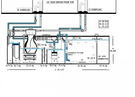
5) UV: I've come to believe that a UV sterilizer is essential equipment for any 90+ gallon reef tank. I don't want to start a debate with people over this here though. However, why not give yourself future flexibility to add a UV (or who knows what else) by building a fancier return pump manifold that has a T junction with a high quality ball valve union coming off the side? You can keep the ball valve closed and it can be connected to nothing for now, but it'll save you a lot of time and headache later if you eventually need to hook up more equipment that runs off your return. For the ball valve, I'd get something like this: https://www.bulkreefsupply.com/cepex-ball-valve.html and use the threaded union for the empty end for easy swap-out.
6) ATO: I'm not clear on whether the ATO is completely isolated or if there's a connection into the refugium
Anyway, sorry for the long reply but hopefully there are a couple useful suggestions in here

Thank you for the compliment on my diagram … I’ve been working on these plans for months…someone said ‘go slow’, so I am trying to think of everything and take my time to do this right! Also thank you for explaining the flow rate situation and helping me to understand it.Thank you for the compliment on my diagram … I’ve been working on these plans for months…someone said ‘go slow’, so I am trying to think of everything and take my time to do this right!
- Draining volume: The reason he said it would depend on flow rate is because flow rate will affect water level in the DT.
- Ok, I think I understand…water is coming in faster than it is draining. The D.T. will fill up faster than it will empty, and the hardwood floors will pay the price…???
Maybe estimate max possible drain volume by measuring height from first siphon break to top rim of your DT and then multiply by width and length?
That’s what I was thinking so I guess my question should be where is the first siphon break? And how many breaks are there? I thought the siphon break was a hole drilled in one of the pipes (drain?)
That's probably overkill because you're not going to want to run your system with water level right at the tip top of your DT.
Well I don’t think it’s overkill, I think you’re right on the money…plan for more water to drain than not and be safer in the long run! I like for the water to be high enough not to show the waterline at the top of the tank! Will this cause a problem?
Yes, there is a lip between the filter socks and the skimmer. It is a 16” piece of glass with a 4” portal at the bottom. It is a 2” lip. I drew it wrong on the diagram, is 2” too high?
- I have had all my glass (3/8”) cut so I won’t be using a kit. I wish I had known before I had it cut. Will the glass work ok?
- Refugium: “drain the refugium via plumbing into the skimmer section”. The skimmer section baffles will handle the bubbles from the refugium return and then you can get rid of the second set of baffles in the pump section which will save you space.
- I’m a little confused…how can I drain the refugium to the skimmer? I understand why…but not how. It sounds logical as to why!!!
I’m not sure about a manifold… I’ll get back to you on that after I research and read about how to plumb it and stuff…
For the ball valve, I'd get something like this: https://www.bulkreefsupply.com/cepex-ball-valve.html
Oh, hey… cool! That’s what kind of ball valves I bought!!!
- ATO: I'm not clear on whether the ATO is completely isolated or if there's a connection into the refugium
- Ok, there are 2 float valves… one in the ATO and one in the refugium…the one in the ATO will be connected to the RO/DI container and the one in the refugium will be connected to the ATO RESERVOIR
- Thank you for your post…Everyone in this reef club is so friendly and helpful…I really appreciate all y’all’s feedback!!!
It's hard for me to tell you where the siphon break will be in your plumbing, but there will be one both in your drain and your return.Thank you for the compliment on my diagram … I’ve been working on these plans for months…someone said ‘go slow’, so I am trying to think of everything and take my time to do this right! Also thank you for explaining the flow rate situation and helping me to understand it.
Draining volume: The reason he said it would depend on flow rate is because flow rate will affect water level in
Ok, I think I understand…please correct me if I'm wrong...water is coming in faster than it is draining. The D.T. will fill up faster than it will empty, and the hardwood floors will pay the price…???
Maybe estimate max possible drain volume by measuring height from first siphon break to top rim of your DT and then multiply by width and length?
That’s what I was thinking so I guess my question should be where is the first siphon break? And how many breaks are there? I thought the siphon break was a hole drilled in one of the pipes (drain?)
That's probably overkill because you're not going to want to run your system with water level right at the tip top of your DT.
Well I don’t think it’s overkill, I think you’re right on the money…plan for more water to drain than not and be safer in the long run! I like for the water to be high enough not to show the waterline at the top of the tank! Will this cause a problem?
Filter sock section: is there a raised lip on the right side of the holder to keep water from flowing over the top into the skimmer section? I can't tell from the drawing. You want one, but not too high so that if the socks get clogged, you can still overflow into the skimmer section (rather than over the top of your sump onto the floor!)
Yes, there is a lip between the filter socks and the skimmer. It is a 16” piece of glass with a 4” portal at the bottom. It is a 2” lip. I drew it wrong on the diagram, is 2”-3" too high?
Baffles: are you going to use adjustable baffles? I'd definitely suggest using kits that have the adjustable ones because it just makes life so much easier for optimizing skimmer performance and working sump volume.
I have had all my glass (3/8”) cut so I won’t be using a kit. I wish I had known before I had it cut. Will the glass work ok?
Refugium: “drain the refugium via plumbing into the skimmer section”. The skimmer section baffles will handle the bubbles from the refugium return and then you can get rid of the second set of baffles in the pump section which will save you space.
I’m a little confused…how do I drain the refugium to the skimmer? I understand why…but not how. It sounds logical as to why!!!
UV: why not give yourself future flexibility to add a UV (or who knows what else) by building a fancier return pump manifold that has a T junction with a high quality ball valve union coming off the side? You can keep the ball valve closed and it can be connected to nothing for now, but it'll save you a lot of time and headache later if you eventually need to hook up more equipment that runs off your return.
I’m not sure about a manifold… I’ll get back to you on that after I research and read about how to plumb it and stuff…
For the ball valve, I'd get something like this: https://www.bulkreefsupply.com/cepex-ball-valve.html
Oh, hey… cool! That’s what kind of ball valves I bought!!!
ATO: I'm not clear on whether the ATO is completely isolated or if there's a connection into the refugium
Ok, there are 2 float valves… one in the ATO and one in the refugium…the one in the ATO will be connected to and control the flow from the large RO/DI container and the one in the ATO RESERVOIR will be connected to and control the flow to the refugium...
Thank you for your long post!!! You've made a lot of concepts more clear for me and I appreciate it. Everyone in this reef club is so friendly and helpful…I really appreciate all y’all’s feedback!!! You might just make a reefer out of me!
(Oh, I have considered the manifold and am working on it now.) What a good idea!!!
Oh. The reason for the disjointed post just before this one is that I had pasted it to the reply form and was working on it when the power went out and it was somehow posted before I finished with it.)


I've found that supplying a fuge from a drain line ends up depositing a lot of detritus in the fuge---which is then a pain to clean. After two tanks doing it that way, I switched on my current tank to feeding my fuge off the return pump. In any case, both methods will workThe only thing I would do differently is instead of using your manifold to supply the fuge, use a T off the drain line and add a valve to it to supply the fuge.

I've found that supplying a fuge from a drain line ends up depositing a lot of detritus in the fuge---which is then a pain to clean. After two tanks doing it that way, I switched on my current tank to feeding my fuge off the return pump. In any case, both methods will work
")