I would love to have done solar tubes. Looked into them years ago but my house just isnt a good fit. Tubes would have to be 15’ long and go up through the middle of my sons room. Probably a non starter; plus living in CT, not sure how useful they’d be anyhow.
Navigation
Install the app
How to install the app on iOS
Follow along with the video below to see how to install our site as a web app on your home screen.
Note: This feature may not be available in some browsers.
More options
You are using an out of date browser. It may not display this or other websites correctly.
You should upgrade or use an alternative browser.
You should upgrade or use an alternative browser.
Tim's 800 Gallon Phoenix Reef
- Monster Build
- Thread starter garbled
- Start date
- Tagged users None
- Joined
- Nov 10, 2018
- Messages
- 772
- Reaction score
- 1,045
Well, you'd probably get something similar to what you saw in that photo. That was taken on an overcast day. It adds alot of color to the tank, so that part is nice. On certain days, the sun beams in at just the right angle and you get some amazing full beams dancing around.
Your son would not appreciate the effect as much as you might though..
Your son would not appreciate the effect as much as you might though..
It's something I would definitely like to try some day. I thought about putting one into my master bedroom, but crawling around on the roof just isn't all that fun as one gets older.
It's something I would definitely like to try some day. I thought about putting one into my master bedroom, but crawling around on the roof just isn't all that fun as one gets older.
It wasn't any more fun when I was young either.
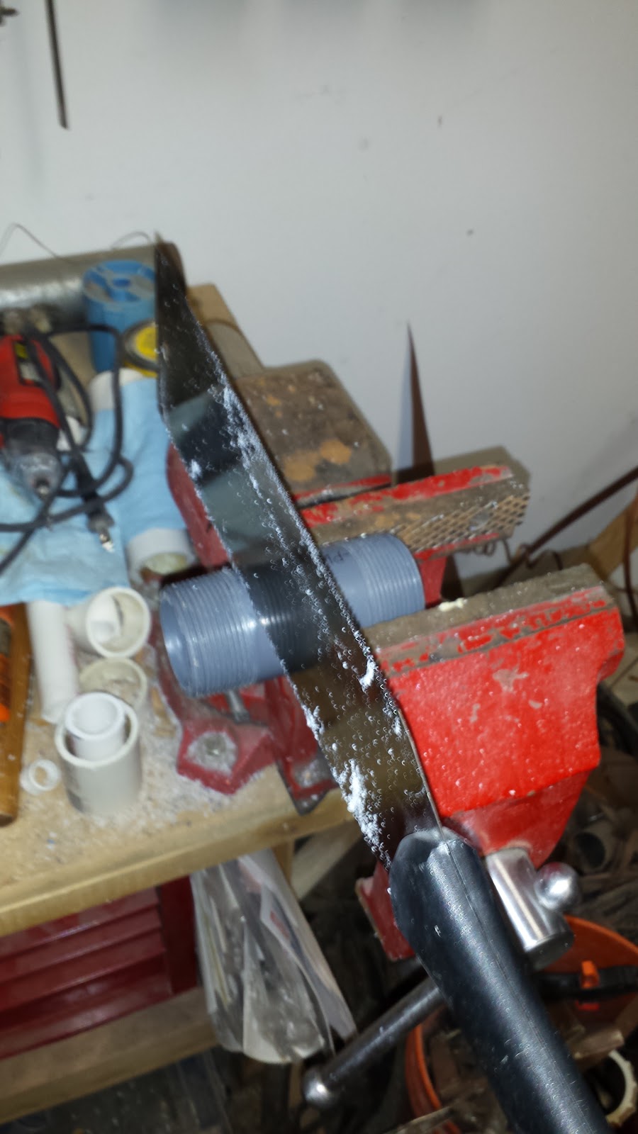
Do you have an example picutre of which Japanese saw you are referring to?
Day 2, PVC glue is created from joy.
Now for the lessons learned portion of our show:
- If you ever buy PVC unions for your tank, buy twice as many as you need. Why do you buy unions? It's because maybe in the future you want to disconnect that thing, and replace it with something else. However, 5-10 years later, what are the chances that the company that made your union is still in business? Now you have a union stuck on something, that you cannot re-use, and you end up having to saw the whole joint off anyhow.
- A Japanese saw, is quite possibly the best tool there is for sawing off random PVC bits. Seriously, made things so much easier than a hacksaw or whatever else.
- PVC pipe nipples (threaded on both ends, the SCH80 stuff) are great to saw in half and convert slip unions into male thread ends.
- Never ever use the type of ball valve shown above. The kind you get from hardware stores. The saltwater gets into the ball, and makes it impossible to turn. I have a few of these with shattered handles. The SCH80 gate valves are great though. Love those.
I've been at it since 4am. Exhausted, I go to bed.
I found that a hole saw bit fits perfectly inside some fittingsFYI I have reused PVC Unions with no leaks many times in the past. The key is finding a metal cylinder that fits into the pvc pipe in the fitting with a bit of clearance. I have used sockets for everything up to 1-1/4" PVC. if you heat the socket up to a very warm (not cherry red) temp using a propane torch then set inside the fitting to warm the pipe and the glue. Remove the metal cylinder and then you can "peel" the PVC pipe away from the inside of the fitting wall with a flathead screwdriver and needle-nose pliers. A bit of cleanup with sandpaper and the fitting is reusable. A $30 Shear gate valve becomes reusable and not throw-away.
So after scrolling through this, i have to say... Thank you. Thank you for not sharing just the wins and the shiny new things you bought and talking about how great blah blah is. You learned a valuable and expensive lesson and shared it. Others will learn from it. Write ups like this are what motivated me with my build and some of the choices i made. I love your enthusiasm and progress. Best of luck this time around.
- Joined
- Nov 10, 2018
- Messages
- 772
- Reaction score
- 1,045
Day 11, Measure twice solder 4 times?
So today a bunch of little tiny parts came in, mostly to do with the lights, and I was off to the races. It was time to finish one of them up, and mount it up above the tank for a test run. I'm probably a month or so away from actually turning them on, but I want to be sure this will work, so, time to drill some holes.
The top end of the sink has some nice M5 holes for mounting a ballast, or other nonsense to, but I'm going to steal that, and instead mount a stainless steel plate 2.5" in diameter I got off Amazon. So I took the plate, drilled a bunch of holes in it, got some stainless steel mounting hardware, and some small ABS spacers, and made myself little hangers.
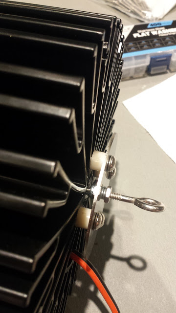
Once the hangers were complete, it was time to mount the LED's to the sink, and bolt it all together. I got some 50mm M3 screws, and used them to mount the light rings I 3d printed, and used the lens assembly and light right to basically mount the LED to the sink. Time to give it a quick test at about 12% power on the floor.
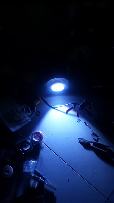

Now speaking of power, I overdid things when I got my ballasts. I didn't quite understand how the Chinese rate LED's, so I got ballasts that were a bit more powerful than I think I'm comfortable running these days. My ballasts are 185 watts. I think realistically these are 133W chips, maybe less, but they run well at 140w, so, lets say 133. So 12% power is really 22W, which is pretty significant. They lit right up, no noticable heat at all.
Now was the time to bolt the hardware (stainless steel again) to the hangers I put in the ceiling, and start hanging a light! I used 1 1/4" washers on the top, and one of those little nuts with the nylon inside that grips the thread better. This should hold a small anvil, so I think I'm good here.

I experimented with various hooks, D rings, and other fiddly bits, but eventually went back to the rope hangers I purchased specifically for this. They were approximately the right length, and the slight adjustability was just about right.

I carefully set the Apex to 15% power, and plugged the ballast in, and...

Woo. I can has light. Lets see how it looks from the front of the tank, and slowly ramp it up.
This is 15%, or 28 watts.
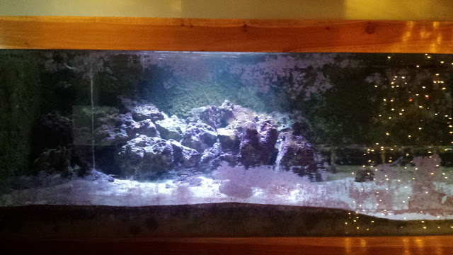
Lets try 30%, (55 watts)
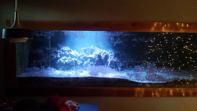
Ok, ok, working so far, lets get crazy and go 50%, 92.5 Watts.

Ooh.. I'm liking it. It's starting to look like it used to. The lights aren't quite as blue as the photos seem to make them, but they are a nice bluish white, which makes me happy. I'm getting about 300 PAR here through the rather dirty acrylic top brace that is directly under this light, and about 1" under water. Heat sink is measuring about 95' F, and a temp probe put directly on the chip is about the same..
Lets try 65% (120 Watts!)
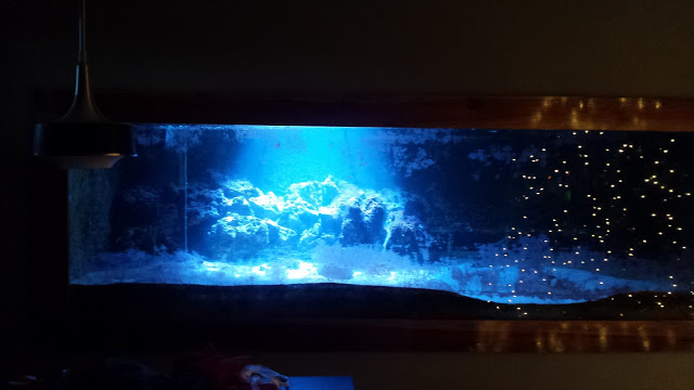
Wooo. Liking this. About 400 PAR 1" under water (dirty brace still). Now the sink is reading about 113 F, and about 117.5F at the chip. These chips are generally happy under 60' C, and 117 is about 47.5 C, so, I'm still good here.
The sinks are *really* good. Like some of the best I've ever worked with in my life. If I take a measurement inside the sink, right above the chip, I get about 113'. If I move all the way to the top, and take a measurement inside the sink (on the central heat tube core again), it's like 112.5. That means the sink is wicking the heat up the full length of the sink, and not just dissapating it all at the bottom. This is exactly what you want these things to do. These are well worth the $104 each I paid for them.
At this point, I get a little nervous, and decide to crank them back down to 60%. (111W). Very little output difference really, but the heat drops to a steady 116' F at the chip. Just out of curiosity, I decide I should measure the heat on my 20W passive cooled chips over my softy tank. Those chips have been running every day for like 6 years now. 147'F. Wow. Just wow. Didn't realize they were running that hot. Either way, I think I like 60% power for now, so I decide I'll let it run for about 3 hours just to be sure it's stable.
The lens holders I printed have some V shaped sides on them, which you can see in a few of the photos. These reflect the light downwards a bit more than just the lenses. In fact, they do such a good job, that the light doesn't quite reach the front glass. I am unsure how happy I am with this tight of a beam. I'll probably have to try it out with all 4 at full running power (which will likely be 60-65%, even though I used to run them at 75%) and see how I like the effect. I also need to get some PAR numbers with all 4 running, but that will be saved for another day.
In the meantime, back to work on the other 3 lights. I cut some leads, this time using 16 AWG wire, instead of 12 AWG, as I just don't need that kind of current handling for the short leads, and they interfere with the lenses a bit. I twist the wire up, and solder up the last 3 LEDs. Now to make the rest of the mounting brackets, and assemble everyone!
I won't go into the full details of the build right now, I'll probably save that for an article. However, because I'm re-using some components from the previous failball, I need to do some cleanup here. The lenses are covered in salt (2 of them from falling into the aquarium), dirt, and 2-3 layers of failed glue. Need to clean all that off, and get the lenses all sparkly clean on the inside before I mount them up.
Also, because I am not exactly Hackaday material with my soldering skills, I had to dremel out a bit of the bottom of each reflector, so the solder joint wouldn't interfere with the lens fitting.

Two of the lights I recently purchased are 50/50 lights instead of the 60/40 blue/white I ran before. Seems the 60/40's are harder to get now, though I did find a line on them in case I need more. But mostly I'm hoping these 50/50's are good enough. The wiring on them does seem different though, so I'm a little unsure as to how they are wired internally. Normally I would snip off the outer tabs on the LED's, but in this case, I'm a bit nervous that they are integral, so I'll be leaving them on the new ones. I'll have to try them out tomorrow or something, and see how the light compares..
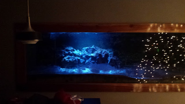
I'll leave you with a fun picture I took right before shutting the system off after the 3 hour test. The lights at 1%, or 1.85 Watts.
Exhausted from hours of holding a temperature probe in a little hole, I shuffle off to bed..
So today a bunch of little tiny parts came in, mostly to do with the lights, and I was off to the races. It was time to finish one of them up, and mount it up above the tank for a test run. I'm probably a month or so away from actually turning them on, but I want to be sure this will work, so, time to drill some holes.
The top end of the sink has some nice M5 holes for mounting a ballast, or other nonsense to, but I'm going to steal that, and instead mount a stainless steel plate 2.5" in diameter I got off Amazon. So I took the plate, drilled a bunch of holes in it, got some stainless steel mounting hardware, and some small ABS spacers, and made myself little hangers.

Once the hangers were complete, it was time to mount the LED's to the sink, and bolt it all together. I got some 50mm M3 screws, and used them to mount the light rings I 3d printed, and used the lens assembly and light right to basically mount the LED to the sink. Time to give it a quick test at about 12% power on the floor.


Now speaking of power, I overdid things when I got my ballasts. I didn't quite understand how the Chinese rate LED's, so I got ballasts that were a bit more powerful than I think I'm comfortable running these days. My ballasts are 185 watts. I think realistically these are 133W chips, maybe less, but they run well at 140w, so, lets say 133. So 12% power is really 22W, which is pretty significant. They lit right up, no noticable heat at all.
Now was the time to bolt the hardware (stainless steel again) to the hangers I put in the ceiling, and start hanging a light! I used 1 1/4" washers on the top, and one of those little nuts with the nylon inside that grips the thread better. This should hold a small anvil, so I think I'm good here.

I experimented with various hooks, D rings, and other fiddly bits, but eventually went back to the rope hangers I purchased specifically for this. They were approximately the right length, and the slight adjustability was just about right.

I carefully set the Apex to 15% power, and plugged the ballast in, and...

Woo. I can has light. Lets see how it looks from the front of the tank, and slowly ramp it up.
This is 15%, or 28 watts.

Lets try 30%, (55 watts)

Ok, ok, working so far, lets get crazy and go 50%, 92.5 Watts.

Ooh.. I'm liking it. It's starting to look like it used to. The lights aren't quite as blue as the photos seem to make them, but they are a nice bluish white, which makes me happy. I'm getting about 300 PAR here through the rather dirty acrylic top brace that is directly under this light, and about 1" under water. Heat sink is measuring about 95' F, and a temp probe put directly on the chip is about the same..
Lets try 65% (120 Watts!)

Wooo. Liking this. About 400 PAR 1" under water (dirty brace still). Now the sink is reading about 113 F, and about 117.5F at the chip. These chips are generally happy under 60' C, and 117 is about 47.5 C, so, I'm still good here.
The sinks are *really* good. Like some of the best I've ever worked with in my life. If I take a measurement inside the sink, right above the chip, I get about 113'. If I move all the way to the top, and take a measurement inside the sink (on the central heat tube core again), it's like 112.5. That means the sink is wicking the heat up the full length of the sink, and not just dissapating it all at the bottom. This is exactly what you want these things to do. These are well worth the $104 each I paid for them.
At this point, I get a little nervous, and decide to crank them back down to 60%. (111W). Very little output difference really, but the heat drops to a steady 116' F at the chip. Just out of curiosity, I decide I should measure the heat on my 20W passive cooled chips over my softy tank. Those chips have been running every day for like 6 years now. 147'F. Wow. Just wow. Didn't realize they were running that hot. Either way, I think I like 60% power for now, so I decide I'll let it run for about 3 hours just to be sure it's stable.
The lens holders I printed have some V shaped sides on them, which you can see in a few of the photos. These reflect the light downwards a bit more than just the lenses. In fact, they do such a good job, that the light doesn't quite reach the front glass. I am unsure how happy I am with this tight of a beam. I'll probably have to try it out with all 4 at full running power (which will likely be 60-65%, even though I used to run them at 75%) and see how I like the effect. I also need to get some PAR numbers with all 4 running, but that will be saved for another day.
In the meantime, back to work on the other 3 lights. I cut some leads, this time using 16 AWG wire, instead of 12 AWG, as I just don't need that kind of current handling for the short leads, and they interfere with the lenses a bit. I twist the wire up, and solder up the last 3 LEDs. Now to make the rest of the mounting brackets, and assemble everyone!
I won't go into the full details of the build right now, I'll probably save that for an article. However, because I'm re-using some components from the previous failball, I need to do some cleanup here. The lenses are covered in salt (2 of them from falling into the aquarium), dirt, and 2-3 layers of failed glue. Need to clean all that off, and get the lenses all sparkly clean on the inside before I mount them up.
Also, because I am not exactly Hackaday material with my soldering skills, I had to dremel out a bit of the bottom of each reflector, so the solder joint wouldn't interfere with the lens fitting.

Two of the lights I recently purchased are 50/50 lights instead of the 60/40 blue/white I ran before. Seems the 60/40's are harder to get now, though I did find a line on them in case I need more. But mostly I'm hoping these 50/50's are good enough. The wiring on them does seem different though, so I'm a little unsure as to how they are wired internally. Normally I would snip off the outer tabs on the LED's, but in this case, I'm a bit nervous that they are integral, so I'll be leaving them on the new ones. I'll have to try them out tomorrow or something, and see how the light compares..
I'll leave you with a fun picture I took right before shutting the system off after the 3 hour test. The lights at 1%, or 1.85 Watts.

Exhausted from hours of holding a temperature probe in a little hole, I shuffle off to bed..
- Joined
- Nov 10, 2018
- Messages
- 772
- Reaction score
- 1,045
Day 11.5, Holy uMol's Batman!
So just a brief update today, mostly because something surprised me.
I decided after the previous light test, that I was worried the lens rings I printed were putting the light out at too narrow of a beam. The easy remedy, would be to print one more, without the focusing ring, and see how it compared to the other light. 5 hours later, I had the new ring, and the light went up on the tank.
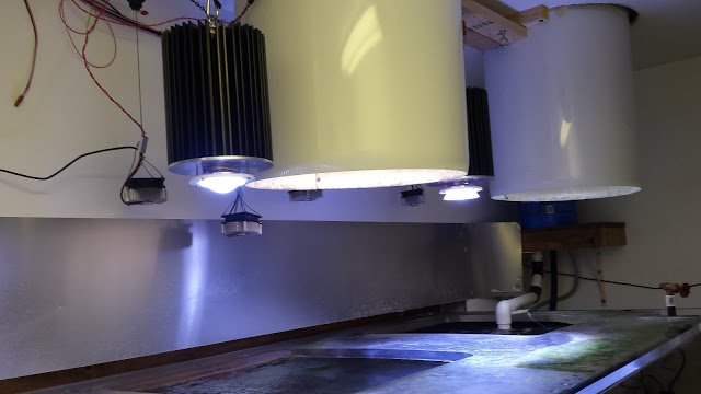
You can see how one of the lenses is fully showing, and the other has the little V ring around it. Both are just opaque white PETG plastic. Nothing fancy here.
So I got out my trust Apogee meter, and set the lights to 45% ( 83 Watts ). Placed the probe right under the original one, with the focus ring, and got a quick reading of 497 or so. Ok, cool. Lets put it under the other one. Will probably be around 300ish, wait, what? 179. Seriously? 179? Oh I must still have this light set at 15%, hrmm, nope, 45%. Maybe this ballast is flaky, swap cables, nope, still 179. Nope. That's the difference of the ring. Slightly less spread to the light, and a doubling of PAR. And it's true more or less at all the different positions. Just better PAR. I suspect less is flying off into the walls and whatnot. But it's totally crazy. I thought the rings would just give me an extra 5% or something, but this is truly nuts. You can even see it in the tank.
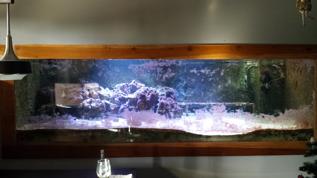
Focusing ring is on the left in this photo. The difference is visually astounding.
So I pulled the new ring off, and went ahead and assembled the rest of the lights with the focus rings that I originally printed, hung them all up, and gave a quick 45% power test:
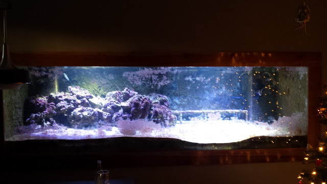
This was taken at night, so the solar tubes aren't helping at all here. They are kind of positioned where the dark areas of the tank on the sides and middle are. I might still need some smaller supplemental lights, or maybe a light bar across the rear, but we will see.
Quick readings around the tank (still at 45% here) give me about 200ish PAR on the rocks, 70 or so on the sandbed. I can live with this for now.
Also did another quick nitrate and phosphate test this morning. Still too high. That Chaeto needs to get to work. Or I need to get to work and get the third fuge online.
Dreaming of Christmas Wrasses and Peppermint Angels, off to bed I go!
So just a brief update today, mostly because something surprised me.
I decided after the previous light test, that I was worried the lens rings I printed were putting the light out at too narrow of a beam. The easy remedy, would be to print one more, without the focusing ring, and see how it compared to the other light. 5 hours later, I had the new ring, and the light went up on the tank.

You can see how one of the lenses is fully showing, and the other has the little V ring around it. Both are just opaque white PETG plastic. Nothing fancy here.
So I got out my trust Apogee meter, and set the lights to 45% ( 83 Watts ). Placed the probe right under the original one, with the focus ring, and got a quick reading of 497 or so. Ok, cool. Lets put it under the other one. Will probably be around 300ish, wait, what? 179. Seriously? 179? Oh I must still have this light set at 15%, hrmm, nope, 45%. Maybe this ballast is flaky, swap cables, nope, still 179. Nope. That's the difference of the ring. Slightly less spread to the light, and a doubling of PAR. And it's true more or less at all the different positions. Just better PAR. I suspect less is flying off into the walls and whatnot. But it's totally crazy. I thought the rings would just give me an extra 5% or something, but this is truly nuts. You can even see it in the tank.

Focusing ring is on the left in this photo. The difference is visually astounding.
So I pulled the new ring off, and went ahead and assembled the rest of the lights with the focus rings that I originally printed, hung them all up, and gave a quick 45% power test:

This was taken at night, so the solar tubes aren't helping at all here. They are kind of positioned where the dark areas of the tank on the sides and middle are. I might still need some smaller supplemental lights, or maybe a light bar across the rear, but we will see.
Quick readings around the tank (still at 45% here) give me about 200ish PAR on the rocks, 70 or so on the sandbed. I can live with this for now.
Also did another quick nitrate and phosphate test this morning. Still too high. That Chaeto needs to get to work. Or I need to get to work and get the third fuge online.
Dreaming of Christmas Wrasses and Peppermint Angels, off to bed I go!
Went went wrong in the beginning....all sounds like normal reefing to me 
- Joined
- Nov 10, 2018
- Messages
- 772
- Reaction score
- 1,045
Day 12, Melancholy and Frustration
Despite multiple stern looks, my old calcium reactor has yet to clean itself. I decided to finally lift it off the garage floor and bring it to the sink. The reactor in question is a 2-stage Reef Octopus CR140D. I feel like it will be a good reactor, even if it's maybe a bit small. Time will tell. I've never actually run it as a calcium rector. Way back whenever, I purchased it to use as a sulfur denitrator. Which it did quite well at honestly, aside from the various horrible problems that sulfur denitrators have. (like trying to kill my fish)
Of course, problems arose. First, I couldn't find the O-rings that seal the top shut. Well.. that's a problem. Luckily, we have the power of the internet. Turns out there is an amazing website called "The O-Ring Store". And yes, they have O-Rings. What kinds you ask? What sizes? Well, all of them. *ALL* of them. So O-rings are measured by the inside diameter of the ring, and then the diameter of the rubber part of the ring. So I took a pair of calipers to my reactor, measured the inside of the groove and the width of the groove, and found it was about 103mm x 3.5mm. Turns out they have that. They also had a few other sizes right around the same dimensions, so I got 3 sets, just in case I measured wrong. 6 O-rings, $9 with shipping. Ok, that's a win.
Back to the cleaning. So now I'm working on the pump, and it looks like the impeller is siezed up inside the shaft. Sigh. A few hours with vinegar isn't helping here, and when I plug it in, I don't even get a baneful hum, so this pump has had it. Well, no big deal, people sell pumps, right?
Kinda. Turns out Reef Octopus stuff is all crazy metric fittings. So now I'm trying to figure out if I have to scrap all the external plumbing, and buy a bunch of crazy adapters, or if there is some other way. Luckily, Coralvue sells a pump called the Aquatrance 2000, which is a replacement for the OTP-2000 in the reactor. They also luckily sell a conversion kit that makes it all fit together. Apparently there are two versions of the OTP-2000, and I have the one that is replaceable. There is another one, with a smaller diameter output, which if I had, I would be SOL. I place the order, and a little message comes up telling me if I place my order between Dec 29th and 31st, it won't ship until Wed the 26th of Jan. I find this odd, because that is a Sunday, so, I wonder what year that message is from? I hope it's not actually true.. sigh..
Quick check on calendar says 2011. So.. Hrmm.
Well, the calcium reactor is clean now, and it has returned my stern looks with a variety of frustrations. I don't need it right away, but this is still annoying. Hopefully it all works out and I don't have to buy another one.
So let's move on to sump #3, the algae fuge. I have an old 25 Gallon tall, from a failed aquarium many many years ago. That particular loss makes me a little sad, as the topoff fitting came loose, sprayed the autofeeder, which went nuts and dumped it's entire contents into the tank, killing everything. It has sat in the corner ever since. I wanted both the rocks, and the tank from this, so, I got to work pulling the rocks out, throwing them in buckets, and then disassembling the rest of the tank. 4 buckets of rocks in total.
This is the part that got to me a bit, as the rocks I pulled from this tank, were also rocks from my original reef tank nearly 20 years ago. Some of them were dead corals from the crash of that tank (AC failure in Arizona, July), and some of them still had epoxied frag plugs on them. Each little skeleton brought back a memory of that specific coral, and I could remember them like it was yesterday. It was a little bittersweet to be outside blasting them with a hose, remembering them.

I miss those brown sticks from back in 2001.
Moving along, I blasted all the rocks clean, and then went ahead and blasted out the tank. It will actually be perfect for the extra sump. I went ahead and ordered a retrofit CPR overflow for it, which I will later silicone in and then drill the back of the tank for an overflow.
Next step was to re-setup my QT tanks. Eons ago I had dreams of a coral farm, so I built this *enormous* shelf. It holds 6 40 gallon breeders, and actually, can hold 2 more on top, but probably needs shallow ones if I were to do something like that. Over the years it became a storage shelf, although I did have 3 breeders sitting on it, so, I cleaned those out, and filled one with saltwater. Threw all the rocks in it so they would cycle, and then tossed on the HOB canister filter I still had for the QT setup. Hrmm, dead. Sigh, ordering a new one, and an impeller, just in case it works. Threw in two random pumps I had lying about instead. (aquasweeps! Anyone remember those?)

I'll have to make up some more salt, and maybe setup a second QT tank, it's not like I have the room for it or anything....

OK, enough wallowing in sorrow for aquariums past. Let's do something useful, or at least pretend to.
First up, I want to throw float switches on the Carlson surge. I want one to go off when the bucket is about to fire, and the other to tell me if it's malfunctioned, and the emergency drain is being used. I built a quick little bracket on my printer, and wired some BRS float switches onto it. Perfect.
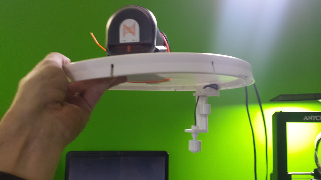
While I was at it, I drilled and cut a few holes in the bucket lid, and zip-tied my new Neptune AFS to the lid. Now the AFS is protected from evil saltwater, and it still drops food right into the bucket! Also, the bucket is now covered so it won't damage my walls anymore, and it's a little bit quieter.
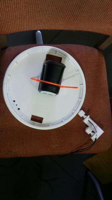
Now I just need to hook all this up to my breakout box that I bought like, a billion years ago and never used. The little tiny wire holders on the older Neptune breakout box are really annoying. I would much prefer fork connects. So I rigged up a little connection bus to make adding more switches easy.
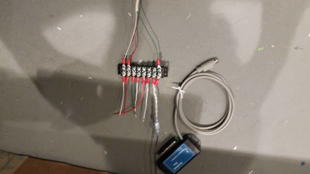
Basically fork connects come in from switches, and then I've pre-wired all the end points to the breakout box. I have 2 connections for the grounds, because they all have to go into one connection.
And now it's all mounted up on the tank room wall, ready to go!

A quick check of the Apex, and yes, every time the surge is about to fire, the switch goes to the OPEN state. Now I can write some cool code to make the Tunze Streams change speeds in concert with the Carlson surge, and really get some water moving around!
A virtual outlet like so:
[Bucket]
Set off
fallback off
if switch OPEN then On
defer 0:30 then OFF
This gives me a 30 second window of time around when the surge fires to turn up the pumps on that side of the tank and give it a little extra boom. Should be fun. Also, since I have one that trips if the emergency drain on the surge is ever used, I programmed that one to shut off the feeder pump to the bucket, to avoid any disasters, and tossed it in the email alarm for peace of mind.
So there is still a bit of time left in the day, so now, it's time to throw some safety at the ATO reservoir. I purchased an AquaFX float valve from BRS awhile back, but then realized I had no way to hook it up inside the reservoir. I also wanted to have a float switch in there, to tell me when the water level was too high, just in case the float valve failed. My goal isn't actually to run the water level up to the float valve, it's more that if it ever runs long enough to fill to that point, hopefully the valve will stop it.
Either way now I needed a way to hook it up. 3D printer to the rescue. Took some careful measurements of the 20g tank, and printed out a nice little bracket to hold the two devices. A few hours later, and joy exists!

Now I hook up all the little bits...

And install into the sump!

Another pressing issue, is the Ruby Elite sump. I ran a side-outlet tube from the main drain, over to the entrance to the refugium area of the sump, which is clear on the other side of the sump. This is super problematic, as basically the water never decides to take that path. I "fixed" it by installing a PMUP in there that takes water out before the skimmer, and sends it off into the fuge. Of course now, the fuge is only processing about 100GPH, so this is really not ideal at all.
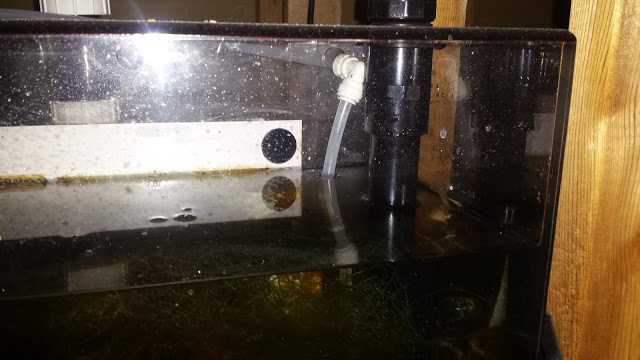
I started looking at the design of this sump, and something occurred to me. The drain pipe has a neat design where it exits deep into the sump, into a little acrylic ring, this presumably keeps it from blasting everything around with water motion. However, because this pipe is fully submerged, it means the water from the drain has to overcome the static pressure of air in there to actually drive water in. Without a full siphon from the dursos, this will never happen.
Solution: Stop the static pressure!

It's just basic 1" PVC, so I cut up an old fitting I took off the tank at some point, and made a nice slant cut in it. Smoothed the edges with a dremel and sand paper, and installed it. The opening sits about halfway in the waterline, and now, water flows through! Not a ton of water, but some water, and a little more helps. I aimed the opening of the slant at the back corner of the fuge, so if it sprays bubbles (and it does), it does so into the acrylic wall, and not into the open air. Perfect, problem made less problematic.
Finally, to finish off my work today, I finally got around to mounting the last of my Christmas presents. A Dragon Touch 10" tablet. Again, 3D printed some brackets I found on thingiverse, and up it went!


Now I have a nice display, right next to the tank, and can know the parameters at a glance, without even having to go into the fishroom. I'm super happy with this.
So in the end, I guess the day ended on a good note. Got alot done, more projects in the works, and probably solved more problems than I uncovered today, so, a win overall.
Feeling hopeful, I trundle off to bed...
Despite multiple stern looks, my old calcium reactor has yet to clean itself. I decided to finally lift it off the garage floor and bring it to the sink. The reactor in question is a 2-stage Reef Octopus CR140D. I feel like it will be a good reactor, even if it's maybe a bit small. Time will tell. I've never actually run it as a calcium rector. Way back whenever, I purchased it to use as a sulfur denitrator. Which it did quite well at honestly, aside from the various horrible problems that sulfur denitrators have. (like trying to kill my fish)
Of course, problems arose. First, I couldn't find the O-rings that seal the top shut. Well.. that's a problem. Luckily, we have the power of the internet. Turns out there is an amazing website called "The O-Ring Store". And yes, they have O-Rings. What kinds you ask? What sizes? Well, all of them. *ALL* of them. So O-rings are measured by the inside diameter of the ring, and then the diameter of the rubber part of the ring. So I took a pair of calipers to my reactor, measured the inside of the groove and the width of the groove, and found it was about 103mm x 3.5mm. Turns out they have that. They also had a few other sizes right around the same dimensions, so I got 3 sets, just in case I measured wrong. 6 O-rings, $9 with shipping. Ok, that's a win.
Back to the cleaning. So now I'm working on the pump, and it looks like the impeller is siezed up inside the shaft. Sigh. A few hours with vinegar isn't helping here, and when I plug it in, I don't even get a baneful hum, so this pump has had it. Well, no big deal, people sell pumps, right?
Kinda. Turns out Reef Octopus stuff is all crazy metric fittings. So now I'm trying to figure out if I have to scrap all the external plumbing, and buy a bunch of crazy adapters, or if there is some other way. Luckily, Coralvue sells a pump called the Aquatrance 2000, which is a replacement for the OTP-2000 in the reactor. They also luckily sell a conversion kit that makes it all fit together. Apparently there are two versions of the OTP-2000, and I have the one that is replaceable. There is another one, with a smaller diameter output, which if I had, I would be SOL. I place the order, and a little message comes up telling me if I place my order between Dec 29th and 31st, it won't ship until Wed the 26th of Jan. I find this odd, because that is a Sunday, so, I wonder what year that message is from? I hope it's not actually true.. sigh..
Quick check on calendar says 2011. So.. Hrmm.
Well, the calcium reactor is clean now, and it has returned my stern looks with a variety of frustrations. I don't need it right away, but this is still annoying. Hopefully it all works out and I don't have to buy another one.
So let's move on to sump #3, the algae fuge. I have an old 25 Gallon tall, from a failed aquarium many many years ago. That particular loss makes me a little sad, as the topoff fitting came loose, sprayed the autofeeder, which went nuts and dumped it's entire contents into the tank, killing everything. It has sat in the corner ever since. I wanted both the rocks, and the tank from this, so, I got to work pulling the rocks out, throwing them in buckets, and then disassembling the rest of the tank. 4 buckets of rocks in total.
This is the part that got to me a bit, as the rocks I pulled from this tank, were also rocks from my original reef tank nearly 20 years ago. Some of them were dead corals from the crash of that tank (AC failure in Arizona, July), and some of them still had epoxied frag plugs on them. Each little skeleton brought back a memory of that specific coral, and I could remember them like it was yesterday. It was a little bittersweet to be outside blasting them with a hose, remembering them.

I miss those brown sticks from back in 2001.
Moving along, I blasted all the rocks clean, and then went ahead and blasted out the tank. It will actually be perfect for the extra sump. I went ahead and ordered a retrofit CPR overflow for it, which I will later silicone in and then drill the back of the tank for an overflow.
Next step was to re-setup my QT tanks. Eons ago I had dreams of a coral farm, so I built this *enormous* shelf. It holds 6 40 gallon breeders, and actually, can hold 2 more on top, but probably needs shallow ones if I were to do something like that. Over the years it became a storage shelf, although I did have 3 breeders sitting on it, so, I cleaned those out, and filled one with saltwater. Threw all the rocks in it so they would cycle, and then tossed on the HOB canister filter I still had for the QT setup. Hrmm, dead. Sigh, ordering a new one, and an impeller, just in case it works. Threw in two random pumps I had lying about instead. (aquasweeps! Anyone remember those?)

I'll have to make up some more salt, and maybe setup a second QT tank, it's not like I have the room for it or anything....

OK, enough wallowing in sorrow for aquariums past. Let's do something useful, or at least pretend to.
First up, I want to throw float switches on the Carlson surge. I want one to go off when the bucket is about to fire, and the other to tell me if it's malfunctioned, and the emergency drain is being used. I built a quick little bracket on my printer, and wired some BRS float switches onto it. Perfect.

While I was at it, I drilled and cut a few holes in the bucket lid, and zip-tied my new Neptune AFS to the lid. Now the AFS is protected from evil saltwater, and it still drops food right into the bucket! Also, the bucket is now covered so it won't damage my walls anymore, and it's a little bit quieter.

Now I just need to hook all this up to my breakout box that I bought like, a billion years ago and never used. The little tiny wire holders on the older Neptune breakout box are really annoying. I would much prefer fork connects. So I rigged up a little connection bus to make adding more switches easy.

Basically fork connects come in from switches, and then I've pre-wired all the end points to the breakout box. I have 2 connections for the grounds, because they all have to go into one connection.
And now it's all mounted up on the tank room wall, ready to go!

A quick check of the Apex, and yes, every time the surge is about to fire, the switch goes to the OPEN state. Now I can write some cool code to make the Tunze Streams change speeds in concert with the Carlson surge, and really get some water moving around!
A virtual outlet like so:
[Bucket]
Set off
fallback off
if switch OPEN then On
defer 0:30 then OFF
This gives me a 30 second window of time around when the surge fires to turn up the pumps on that side of the tank and give it a little extra boom. Should be fun. Also, since I have one that trips if the emergency drain on the surge is ever used, I programmed that one to shut off the feeder pump to the bucket, to avoid any disasters, and tossed it in the email alarm for peace of mind.
So there is still a bit of time left in the day, so now, it's time to throw some safety at the ATO reservoir. I purchased an AquaFX float valve from BRS awhile back, but then realized I had no way to hook it up inside the reservoir. I also wanted to have a float switch in there, to tell me when the water level was too high, just in case the float valve failed. My goal isn't actually to run the water level up to the float valve, it's more that if it ever runs long enough to fill to that point, hopefully the valve will stop it.
Either way now I needed a way to hook it up. 3D printer to the rescue. Took some careful measurements of the 20g tank, and printed out a nice little bracket to hold the two devices. A few hours later, and joy exists!

Now I hook up all the little bits...

And install into the sump!

Another pressing issue, is the Ruby Elite sump. I ran a side-outlet tube from the main drain, over to the entrance to the refugium area of the sump, which is clear on the other side of the sump. This is super problematic, as basically the water never decides to take that path. I "fixed" it by installing a PMUP in there that takes water out before the skimmer, and sends it off into the fuge. Of course now, the fuge is only processing about 100GPH, so this is really not ideal at all.

I started looking at the design of this sump, and something occurred to me. The drain pipe has a neat design where it exits deep into the sump, into a little acrylic ring, this presumably keeps it from blasting everything around with water motion. However, because this pipe is fully submerged, it means the water from the drain has to overcome the static pressure of air in there to actually drive water in. Without a full siphon from the dursos, this will never happen.
Solution: Stop the static pressure!

It's just basic 1" PVC, so I cut up an old fitting I took off the tank at some point, and made a nice slant cut in it. Smoothed the edges with a dremel and sand paper, and installed it. The opening sits about halfway in the waterline, and now, water flows through! Not a ton of water, but some water, and a little more helps. I aimed the opening of the slant at the back corner of the fuge, so if it sprays bubbles (and it does), it does so into the acrylic wall, and not into the open air. Perfect, problem made less problematic.
Finally, to finish off my work today, I finally got around to mounting the last of my Christmas presents. A Dragon Touch 10" tablet. Again, 3D printed some brackets I found on thingiverse, and up it went!


Now I have a nice display, right next to the tank, and can know the parameters at a glance, without even having to go into the fishroom. I'm super happy with this.
So in the end, I guess the day ended on a good note. Got alot done, more projects in the works, and probably solved more problems than I uncovered today, so, a win overall.
Feeling hopeful, I trundle off to bed...
Thanks for the encouragement. It's been an eyesore in my home for awhile now, and it's bothered me alot. Honestly, I just kept thinking, "I'll go buy some plywood, and glass, and this and that and make giant sumps to fix it." But I never did. Just kept putting it off because it was too much work. And the funny thing is, my logic is "well, sumps are expensive, I can DIY that, make it perfect, and save a few hundred $$$, it will just take me X years and I'll never actually do it." This kind of savings is not a thing.
My intention for this thread is not really to show off the tank. It's more to document that mistakes are made, and I can do things differently to avoid said mistakes in the next iteration. (one assumes I will make additional mistakes, but lets hope they are less awful) Every single thing I'm doing on this rebuild has a "how will this fail?" thought process that goes into it first. For example, the Apex was great at managing the RO/DI ATO, but what the Apex couldn't manage was "what if the connector snaps in half, at 3am, on the high pressure side?" The *really* scary part of that story, is I was leaving for a 11 day road trip that morning. So if it had broken 8 hours later, my house would be in a lake bottom. Apex's are great, amazing. Put a leak detector sensor on there, have it tell you that you have a leak. But lets say I was 800 miles away and it told me "you have issues". What would I have done exactly?
This was compounded by the fact that the sumps were awful. So I got used to a little stupid on the floor every now and again. It's concrete, who cares? Never, ever, ever get used to that. Fix it.
- Don't use an Apex to control an infinite source of water. If you have an infinite source, it will absolutely, eventually dump into your home. It's not the Apex's fault here. The Apex didn't shatter the fitting, but the Apex couldn't do anything once it broke. If the Apex can't solve it, the Apex shouldn't operate it.
- If you get used to spills and water mishaps, you will eventually miss a big one.
- On something of this size, hell, anything really, never place electrical powerstrips or mains interfaces underneath and inside the perimeter of the tank. Lets say you are feeding, and you splash a tiny bit of water on the edge. That water slowly creeps down the side, into the side of the stand, and then inevitably finds it's way to the cord or plug. Sure, you have a drip loop, but what if the water comes down the side of the stand and just goes right into the strip? Go look at your powerstrip, is there salt on it?
- Ideally, electrical connections should be made where the surface that holds the connection, does not physically contact the aquarium itself. For example, a small tank on a stand. The wall behind the stand isn't touching the tank, nor the stand. So this means salt and water can never drip down it. This is where the drip loop saves you. Not inside the stand. Mind you, if you splash on the wall you still lose, but we have to have an outlet somewhere..
- Sumps splash. That means salt sprays everywhere. USB cables on Apex's are steel. Steel rusts. Rust bridges connections inside the Apex or the EB8's. Those connections aren't waterproof, don't treat them like they are. Humidity + salt == rust.
- Salt creep down the side of the tank is unattractive. This might not matter to you much if it's on the back and you can't see it. However, the hidden danger of salt creep is that it is like a little river for saltwater. Every drop that adds to the creep, adds it at the bottom, and more water slowly follows the path all the way down, until, like some sort of bizzare gravity, it locates an expensive thing and feeds water into it.
- Computer fans suck. Well, maybe not, but they hate humidity and they hate salt.
- A humid room, with a lot of saltwater in it, produces this bizarre salty dust that gets on everything. It's kinda brown and gunky and like a form of dust that forms clumps. This horrid substance likes to attach itself to things like fan blades, or heatsink fins. With fan blades, it eventually ruins the fan, usually because the weight builds up until the fan begins to wobble on the motor and grinds a bearing to dust. With heatsink fins though, the problem is worse. If you have a computer heatsink, they are amazingly well designed to transfer heat, but they are not designed with the idea that dust is sticky goop. On your computer you aim a dust thing at it and the dust goes away, and the flow is unclogged. In a reef room, that dust just clogs up and you cannot get it out easily. This means you should never use a heatsink that has thin blades. The goop gets down into those blades and clogs them in ways you cannot fix easily. All heatsinks should be large finned so you can the the goop off.
- DIY LED's are amazing. I will be resurrecting mine absolutely. However, if an LED relies on a fan to keep the heatsink cold, you need to assume right up front that it will fail and the LED will turn that lovely black color they like to do. All heatsinks should be passive. I have another tank with some DIY 20W SMD's on it, all on passive heatsinks. They work wonderfully. No active cooling for LED's. Always passive.
@JumboShrimp - Oh, the pun was intended.Even the name of the thread, I live in Phoenix, and this tank will rise from the ashes of a small electrical fire.
@Scott Jeffries - The plan has always been for SPS. I will stick to that plan.
Thank you to everyone for the words of encouragement. I can make this work again, it's just going to take effort and $$$. Back to the plumbing mines for now. I do have to say, the nice thing about keeping reef aquariums for 20+ years, is you build up this amazing supply of PVC fittings, and can just pull the 3 20g totes out and find what you need immediately.
My god this story is making me relive my tank from 2001. Brute trashcan sumps, that saltwater dust you mention, rusty apex gear. Congrats for turning the corner!
In reading the section where you lived with the ato alerts all day, I thought about how some of my non-mission critical alarms are set up - with a virtual output between the cause of the alarm and any fixes, and the alarm or email outlet. If I get an alert during the day that my calcium is low, I just shut off that virtual outlet and the email alert stops. The dosing pump remains off (or whatever) but no more alarms. Get home, refill, reset the virtual outlet to auto and back in business.
- Joined
- Nov 10, 2018
- Messages
- 772
- Reaction score
- 1,045
I thought about how some of my non-mission critical alarms are set up - with a virtual output between the cause of the alarm and any fixes, and the alarm or email outlet
That's a good idea. I'm still tuning some of the more fiddly systems in the tank. For example, it's starting to get cold out now, so last night the heater overrun alarm went off. I have a "When ON > 60:00 Then OFF" statement in there.
The new Apex "When" statement is great, and awful all at once. What it does is act like a circuit breaker, so at 2am, when it's super cold out, the heater runs for an hour, shuts off, (and that means the slider moves to the full OFF position) and then the alarm goes off. So in my case, I just have to reset the slider back to auto. Problem is it's 2am.
It will just take time to find out what the real numbers are. I think that I needed to get 500W heaters, not 300's, and because I have 300's, I need to swap them over to about 75 minute max runtimes this month.
The ATO still befuddles me a bit. I'm still unsure what my real evap rate is. I need to play a bit more and take actual measurements there.
Have you been to Artistic Aquariums in Chandler? I thought it looked nice when I was out there over Thanksgiving.


Similar threads
- Replies
- 117
- Views
- 3,162
- Replies
- 0
- Views
- 92
- Replies
- 38
- Views
- 2,211


