- Joined
- Aug 14, 2019
- Messages
- 4,198
- Reaction score
- 12,164
Do it and let us know how it ends up.I have a question, Can I pour a bunch of water on an electrical socket and put my finger in it? Thanks if you answer!
Follow along with the video below to see how to install our site as a web app on your home screen.
Note: This feature may not be available in some browsers.
Do it and let us know how it ends up.I have a question, Can I pour a bunch of water on an electrical socket and put my finger in it? Thanks if you answer!
Just to follow up on this... I don't have the 2020 NEC yet, I need to order one. But, per the 2017 NEC 200.4 (A) Installation. Neutral conductors shall not be used for more than one branch circuit, for more than one multiwire branch circuit, or for more than one set of ungrounded feeder conductors unless specifically permitted elsewhere in this Code.
The 2 exceptions in the code are in 215.4 for polyphase feeders and 225.7 for outdoor lighting.
I have a collection of NEC's going back to 2004 so I was able to determine that this practice was eliminated in the 2014 NEC.
I agree. The electrical theory is sound that you can't overload the neutral as long as you have the 2 hots that are 180 out of phase.I didn't disbelieve you, but I don't see the point to this rule, except that it would be possible to move one of the hot wires to another breaker on the same phase and overload the neutral. ( I have seen this )
My impression of the NEC is they have generally moved to making all circuits discrete and separate. Presumably for the reason @Brew12 mentioned above. There are plenty of non-electricians who retire outlets, etc. If you have 2 circuits on one neutral, you can easily end up with a hot neutral wire even though the breaker for the outlet you’re working on is turned off. It’s not terribly unlike the rule that says the neutral and ground need to be separate for a sub panel.Probably the people who make copper wire had something to do with it
I think it had something to do with people getting shocked off the neutral even when the breaker was off. But those people who don't know what they are doing should not mess with electricity.
But those people who don't know what they are doing should not mess with electricity.


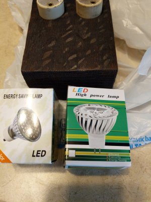
Hah, well that's part of the problem now. I know enough to know when to ask for help. They came in a plastic bag, and I've never wired anything like this before. I was following someone else's suggestion when I bought this stuff a few years ago, and I'm ok with pulling the plug on the whole idea.It should say on the box and on the lamps themselves what the voltage is. If you don't know what the voltage is how are you going to wire them?
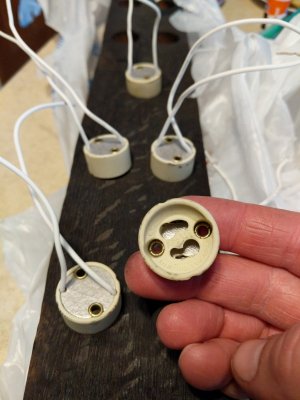
GU10 ceramic bases are rated to 250VAC if they are made to specification. If they are plastic, they are fake and I would toss them.Hah, well that's part of the problem now. I know enough to know when to ask for help. They came in a plastic bag, and I've never wired anything like this before. I was following someone else's suggestion when I bought this stuff a few years ago, and I'm ok with pulling the plug on the whole idea.
They are ceramic, they just came bundled in a plastic bag.GU10 ceramic bases are rated to 250VAC if they are made to specification. If they are plastic, they are fake and I would toss them.
They should be fine to use on a 110V system then.They are ceramic, they just came bundled in a plastic bag.
I was more worried about the bulbs he was using - it sounded like he didn't know the voltage of the bulbs. I'm not sure if they make low-voltage GU10 bulbs but if he has a 12V bulb and wires it to 120V it might get interesting.They should be fine to use on a 110V system then.
Hopefully the voltage for the bulbs is marked on the boxes since he has those.I was more worried about the bulbs he was using - it sounded like he didn't know the voltage of the bulbs. I'm not sure if they make low-voltage GU10 bulbs but if he has a 12V bulb and wires it to 120V it might get interesting.
The description you posted shows the pump drawing 4.8w, or 400mA at 12V. It doesn't say how much more power the controller itself uses; the power supply you show is rated too 12W. Without knowing more you should have at least a 12W supply to replace it. The information you posted on the step up converter cable also doesn't list the power rating.I need to replace the power supply that came with my Duetto ATO. A micro controller + DC pump.
It's just way too big. It says its 12V and 1amp (it has a 5.5mm/2.1mm barrel plug).
Can I replace it with this USB adapter plus a step up converter cable?

If not any other solutions? I can't come across a wall wart any less than 1.2" in depth.

Hi - very basic question - I have 3 cabinet doors on my stand and need to know how to ire the 3 magnetic switches so that opening any of the doors turns on the lights. I know next to nothing about wiring, so telling me to wire them in parallel or in series does not mean anything to me...... I have searched on the web and see lots of help for wiring one switch, but not multiple switches. Thanks in advanceNot at all, will be glad to helpalso you will find out there will be others that will help

Are you connecting this to an Apex, some other controller or trying to make a DYI switch? Also, what kind of magnetic switches do you have? (most are the same, but without knowing for sure it's hard to say with certainty what you should do)Hi - very basic question - I have 3 cabinet doors on my stand and need to know how to ire the 3 magnetic switches so that opening any of the doors turns on the lights. I know next to nothing about wiring, so telling me to wire them in parallel or in series does not mean anything to me...... I have searched on the web and see lots of help for wiring one switch, but not multiple switches. Thanks in advance
