

Hi All,
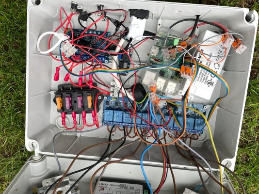
I thought i would share my current build and welcome any feedback as to changes and the like. I must say i bought this from Facebook market place and wipe the card on the PI and started from scratch for the config. I will at some point be tidying up the wiring. I have had to check all connections as there were a few lose wires.


I thought i would share my current build and welcome any feedback as to changes and the like. I must say i bought this from Facebook market place and wipe the card on the PI and started from scratch for the config. I will at some point be tidying up the wiring. I have had to check all connections as there were a few lose wires.


")


