MakersLED diy build

Curtie44

Active Member
View Badges
Joined
Jun 30, 2009
Messages
373
Reaction score
264
Location
Martinsburg, WV
Rating - 0%
0   0   0
I've been wanting to switch to an LED fixture for some time now and finally decided to go for it. I figured I would start with the 40G frag tank in the basement before I tried to tackle the 120 main display upstairs; I wanted to make sure I would be happy with the color and coverage first. I decided on the MakersLED heat sink because unlike most of the other heatsinks out there, this one actually looks pretty good, as close to a regular light fixture you can get without the awful DIY look. LEDGroupBuy.com is where I got the fixture, drivers and LED's.

IMG_9768_zps3bb73849.jpg


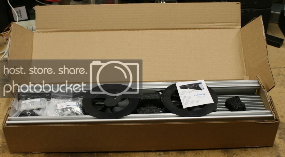
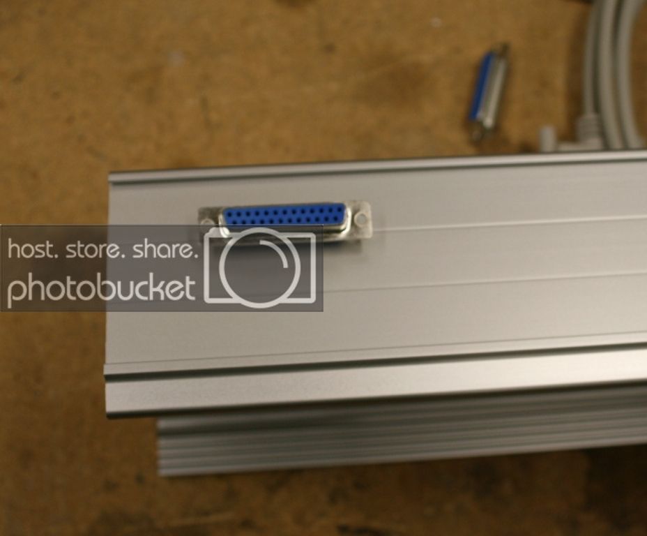
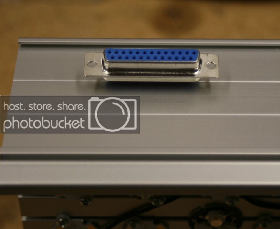
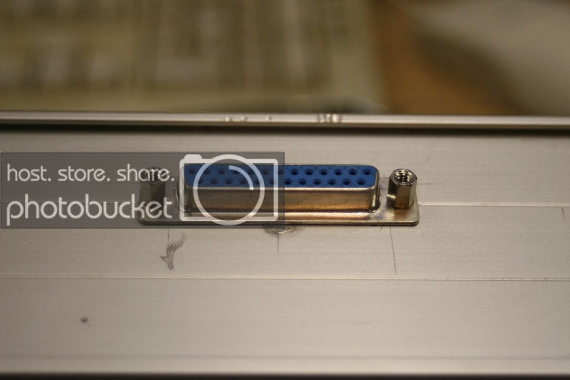
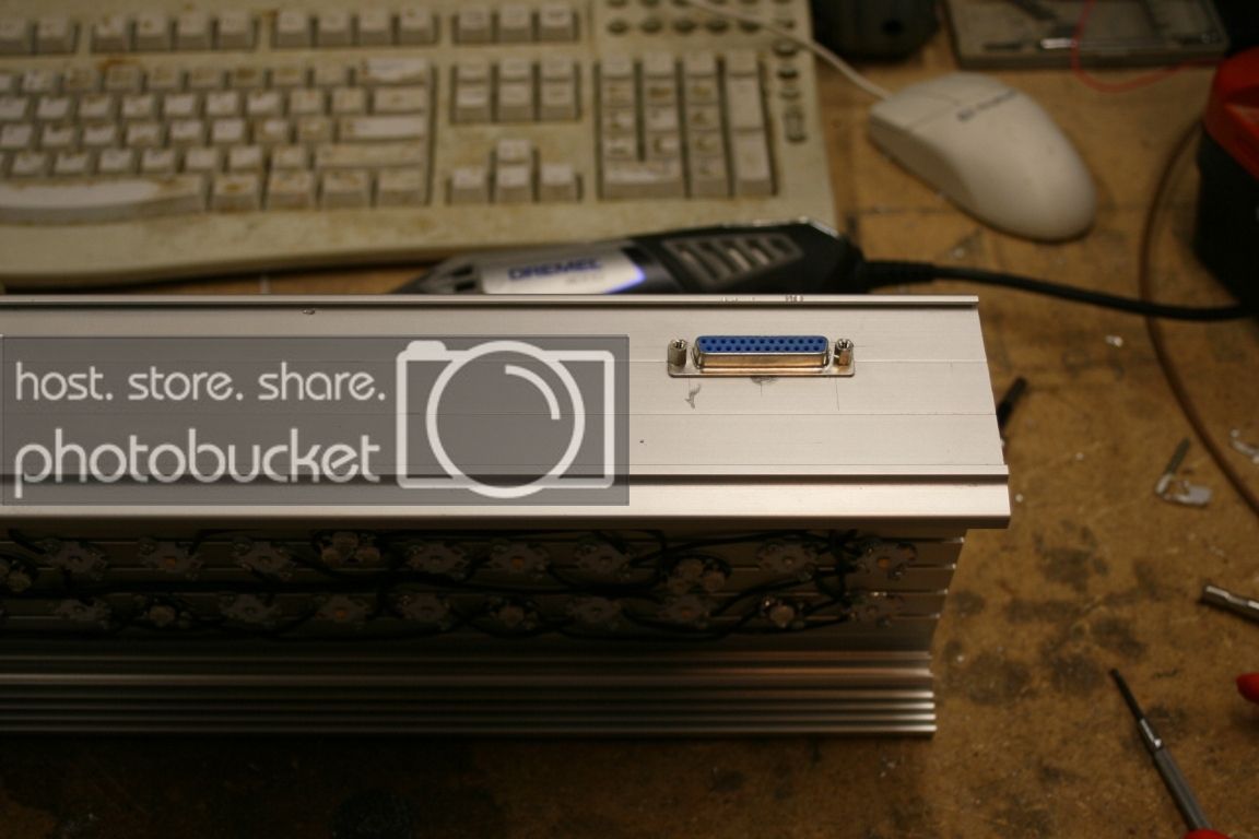
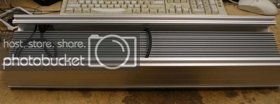
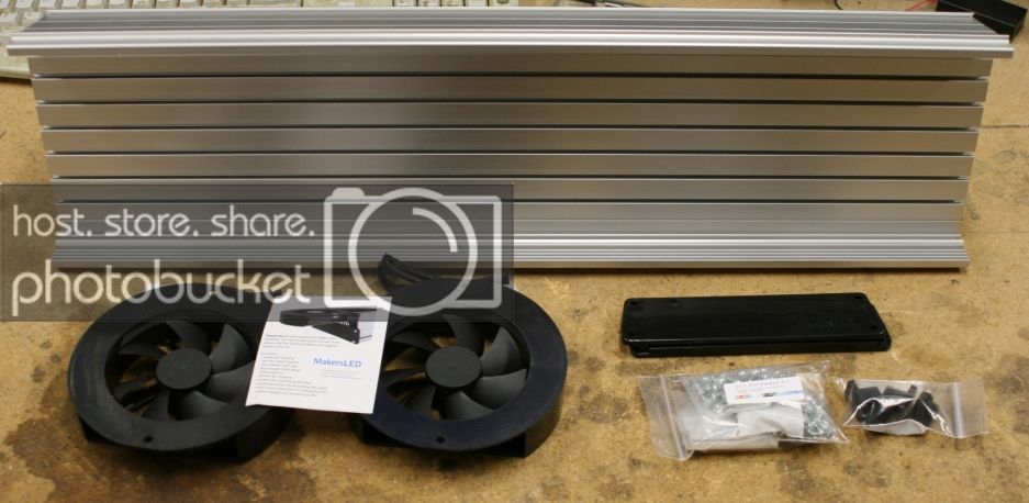
The heatsink comes with 1 cooling fan and enough hardware for 25 LED's for every 12" of heatsink. They also include endcaps to give the fixture a nice clean look and a clear lexan shield that acts as a splash shield.

IMG_9769_zps5c192ce3.jpg


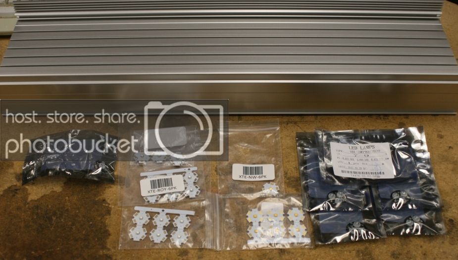
My LED choices ended up being:

30 Cree XT-E Royal Blue
15 Cree XT-E Neutral White
12 Exotic Hyper Violet
5 Exotic Ocean Coral White OCW combine 3 LED's on one star, Deep Red, Turquoise and cool Blue.

IMG_9770_zps50c7c0a4.jpg


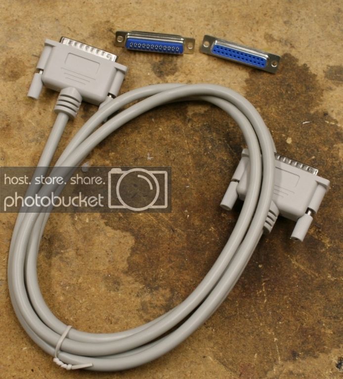
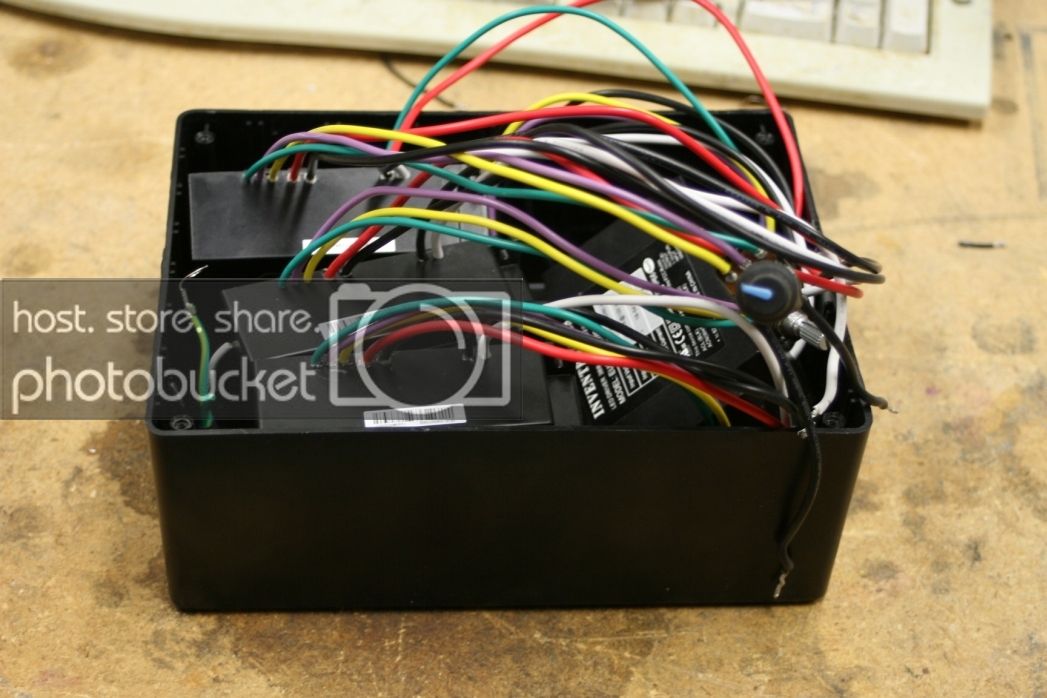
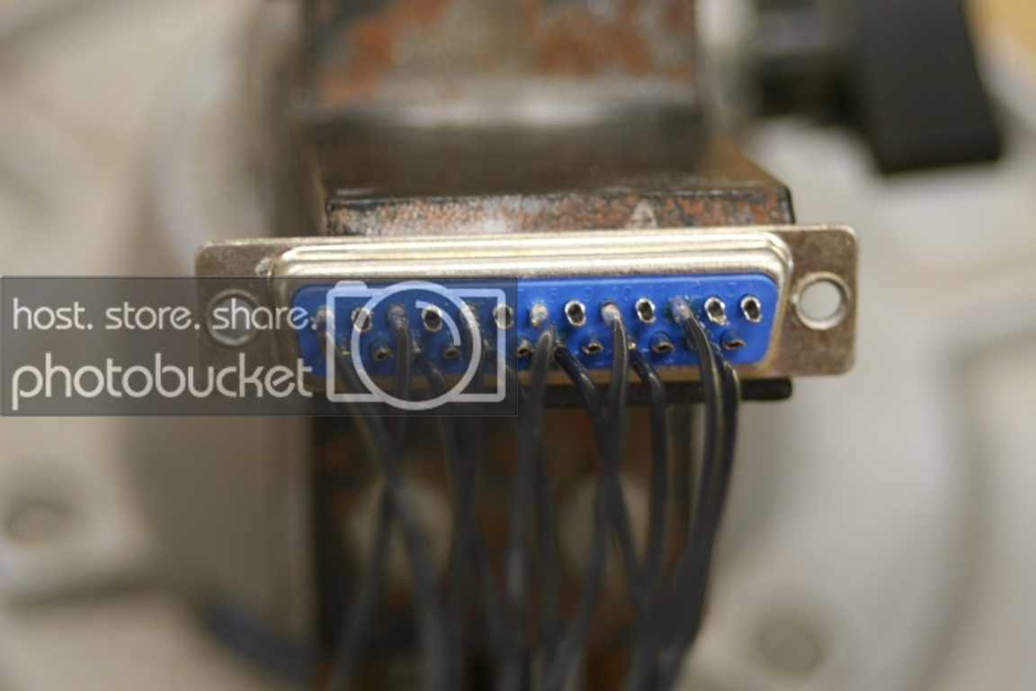
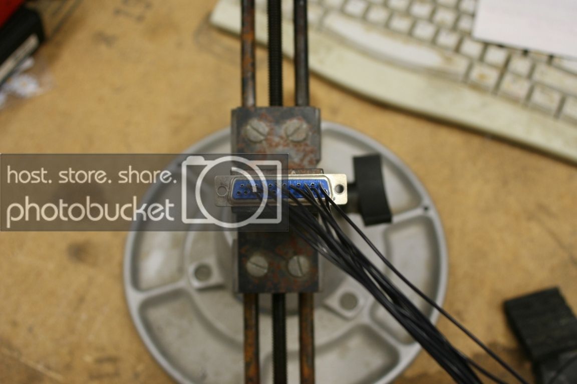
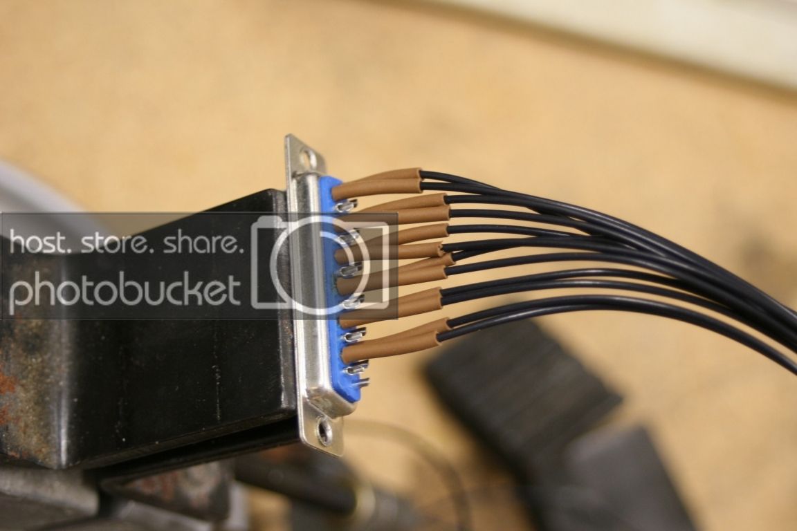
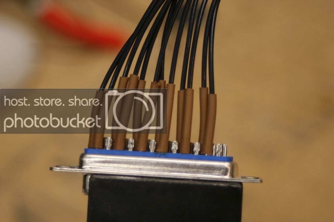
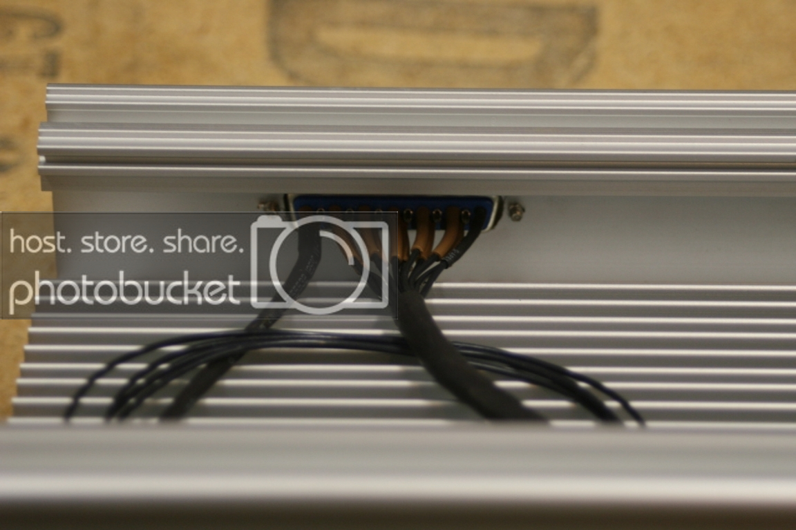
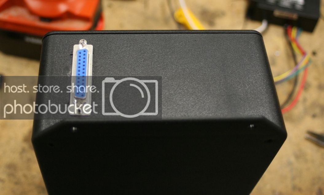
I went with Inventronics dimmable drivers I'll have all channels controlled separately, so RB, NW, OCW and HV all independently dimmable.


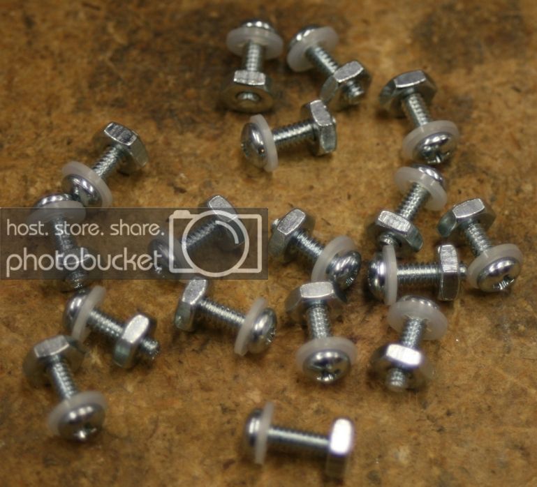
The next step was to assemble all the hardware...This part really stinks.

IMG_9773_zps8641861c.jpg


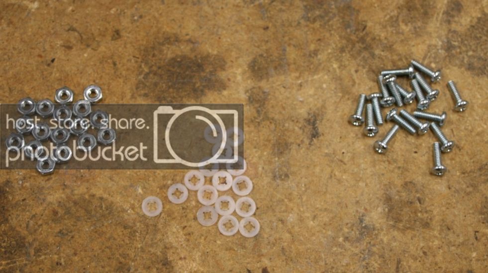
62 LED's x 2 screws per LED = Sore fingers after all plastic washers and nuts are assembled to the screws

IMG_9774_zpsc8db9764.jpg


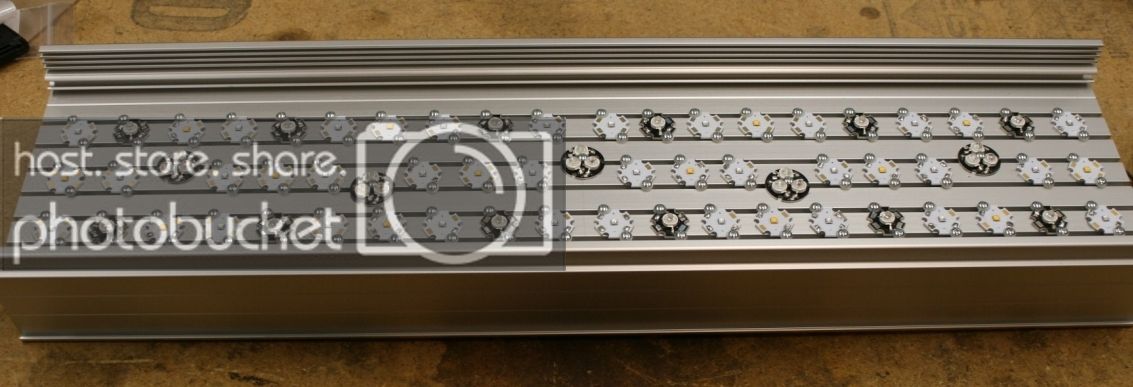
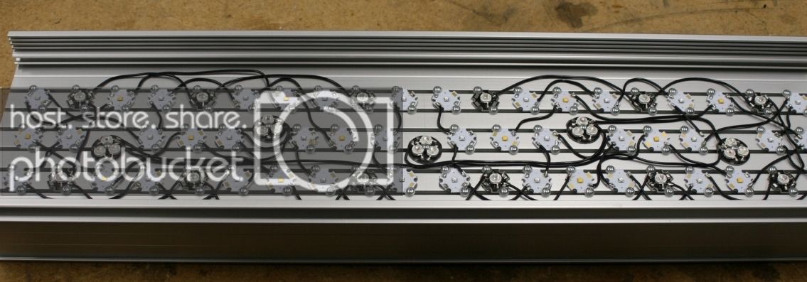
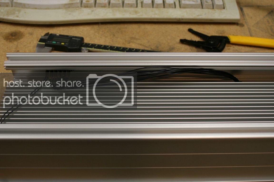
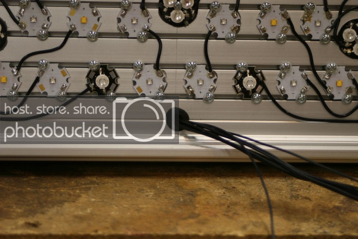
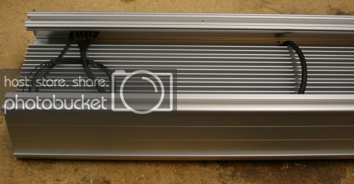
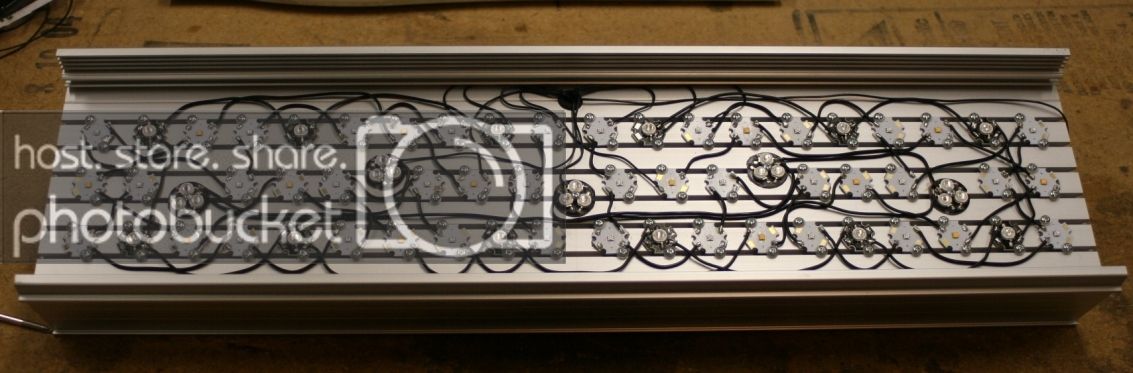
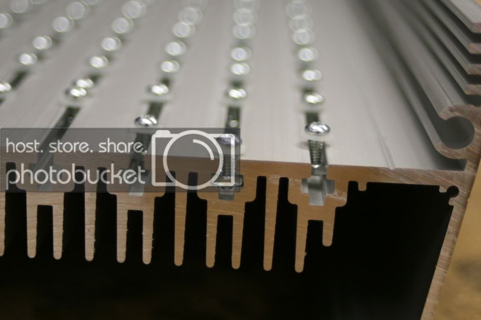
The hardware slides down the slots in the heatsink, making mounting your stars a snap.

IMG_9775_zps59f7a8d3.jpg


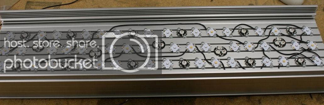
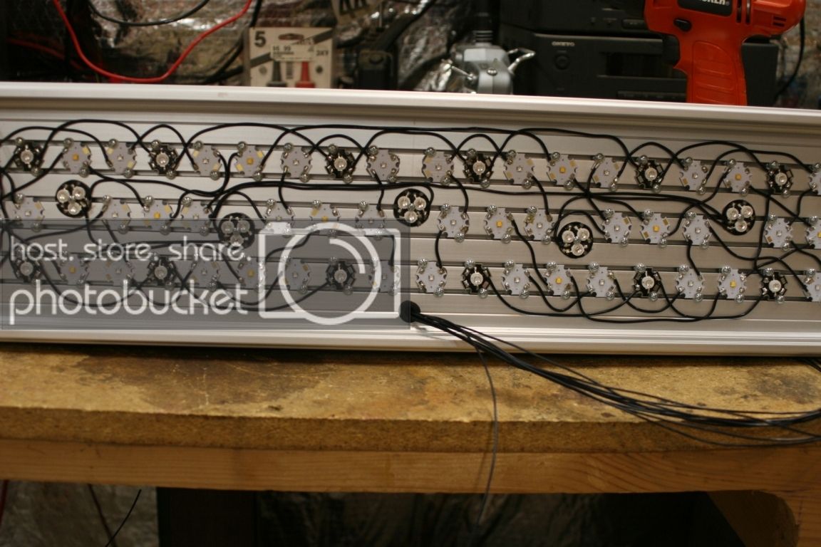
So here's my initial layout. The first three in top row left to right are RB, HV, NW. First three in middle row are NW, RB, OCW.

IMG_9779_zps4ec9bfb1.jpg


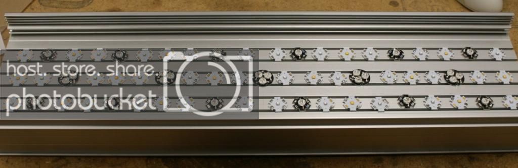
Next I have to add the thermal compound and hardware to lock the LED's in place. I guess I beter get to it ;)
 

Singlefin

Valuable Member
View Badges
Joined
Mar 21, 2012
Messages
1,068
Reaction score
150
Location
Pacific
Rating - 0%
0   0   0
Very nice. I have the same Heatsink. I really like it. Looking good.
 

cdness

2006 - Present
View Badges
Joined
Jul 15, 2009
Messages
3,988
Reaction score
165
Location
West Fargo, ND
Rating - 0%
0   0   0
What length is this? Keep the pics coming. I want to see it on the tank. Do you mind letting us know the materials cost in the end?
 
OP
OP
Curtie44

Curtie44

Active Member
View Badges
Joined
Jun 30, 2009
Messages
373
Reaction score
264
Location
Martinsburg, WV
Rating - 0%
0   0   0
Very nice. I have the same Heatsink. I really like it. Looking good.

Thanks...the tedious work is about to begin. I did a quick read thru your build thread. Yours turned out really nice. I'm interested to know what type of cableing you used to connect your fixture to your drivers. I was planning on using a some db-15 connectors and soldering up a cable, but yours looked pretty clean too...what did you use?
 
OP
OP
Curtie44

Curtie44

Active Member
View Badges
Joined
Jun 30, 2009
Messages
373
Reaction score
264
Location
Martinsburg, WV
Rating - 0%
0   0   0
What length is this? Keep the pics coming. I want to see it on the tank. Do you mind letting us know the materials cost in the end?

This is the 24" heat sink. I will take pics of each step along the way. I don't mind sharing the total cost once it's done...I think so far I'm about $475 in materials for this build.
 
OP
OP
Curtie44

Curtie44

Active Member
View Badges
Joined
Jun 30, 2009
Messages
373
Reaction score
264
Location
Martinsburg, WV
Rating - 0%
0   0   0
I got the thermal paste on and all the LED's locked down with the 4-40 screws.

IMG_9780.jpg


Then came soldering all the strings...it's getting messy really fast. I have all the Neutral white done and half of the Royal Blue. I have to split the RB into 2 strings because the drivers can only handle about 15-18 LED's per string. I still have the Hyper violet, the other half of the Royal Blue and the OCW's left to do.

IMG_9784.jpg
 
OP
OP
Curtie44

Curtie44

Active Member
View Badges
Joined
Jun 30, 2009
Messages
373
Reaction score
264
Location
Martinsburg, WV
Rating - 0%
0   0   0
How is your project coming? I would like to see how it's going.

Well, unfortunately I didn't get any more soldering done this week. I did however, pick up some more stuff for the project. I stopped by my local electronics store and got 2 DB-25 connectors and a DB-25 serial cable.

IMG_9789_zps5caaca14.jpg


IMG_9790_zps76e27614.jpg


I'll use this to connect the drivers remotely so they are not on top of the fixture. The plan is to cut a hole in the fixture to accept the DB-25, then sloder wires from the connector to the leds themselves.

IMG_9791_zps9295906a.jpg


IMG_9792_zps1301bc33.jpg


On the other end, I'll use the other connector to do the same in a project box where all the drivers will be placed.

IMG_9793_zpse734b48b.jpg


This is a project box I picked up from Radio Shack, but as it turns out it is going to be way too small for all 5 drivers plus the wiring. A buddy of mine suggested a website called polycase.com. They have all sorts of plastic enclosures for this kind of thing. I think I'm going to go with this one: DC-96F DC Series Heavy Duty Electronics Enclosure

The next decision is, do I want to run the wires for the potentiometers (dimming) out to the fixture, or just drill holes in the box and mount them in there? My original plan was to mount them in the box. From everything I've read of others DIY builds, once you get the lights dimmed to your color liking you rarely ever mess with it again. So does it really need to be on the fixture? I guess this will come down to the WAF.

I should be able to finish soldering up all the LED's this weekend so hopefully I will have some good progress to share.
 

Jlobes

5000 Club Member
View Badges
Joined
Jun 30, 2012
Messages
5,997
Reaction score
1,250
Location
Behind the redwood curtain
Rating - 0%
0   0   0
slick looking build. I'm not the electronics tinkerer, but I always wanted to see a DIY that looked super clean. with just a single wire and no mounted drivers. keep it up.
following.
 

Dave A

Active Member
View Badges
Joined
Dec 30, 2012
Messages
113
Reaction score
3
Location
NJ
Rating - 0%
0   0   0
Well, unfortunately I didn't get any more soldering done this week. I did however, pick up some more stuff for the project. I stopped by my local electronics store and got 2 DB-25 connectors and a DB-25 serial cable.

I'll use this to connect the drivers remotely so they are not on top of the fixture. The plan is to cut a hole in the fixture to accept the DB-25, then sloder wires from the connector to the leds themselves.

On the other end, I'll use the other connector to do the same in a project box where all the drivers will be placed.

This is a project box I picked up from Radio Shack, but as it turns out it is going to be way too small for all 5 drivers plus the wiring. A buddy of mine suggested a website called polycase.com. They have all sorts of plastic enclosures for this kind of thing. I think I'm going to go with this one: DC-96F DC Series Heavy Duty Electronics Enclosure

The next decision is, do I want to run the wires for the potentiometers (dimming) out to the fixture, or just drill holes in the box and mount them in there? My original plan was to mount them in the box. From everything I've read of others DIY builds, once you get the lights dimmed to your color liking you rarely ever mess with it again. So does it really need to be on the fixture? I guess this will come down to the WAF.

I should be able to finish soldering up all the LED's this weekend so hopefully I will have some good progress to share.
Just a couple thoughts. First; IIRC, those drivers can run up to 60V. Is the DB-25 cable able to handle that? I thought I had read that this connector was only good up to 36V. I never did find a max current rating for it, I've read anything from 500mA to 5A from different sources. Second; I have not used those drivers but all the drivers I have used have produced heat, not a lot of heat, but some heat none the less. Will you be venting the enclosure?
 

ReefLEDLights

Valuable Member
View Badges
Joined
Jul 12, 2011
Messages
1,594
Reaction score
195
Location
IL
Rating - 0%
0   0   0
I like the DB 25 Connector. Keeps wiring clean.

Just make sure they are tight. An intermittent connection with the Inventronics class of driver will damage the LEDs.

Bill
 
OP
OP
Curtie44

Curtie44

Active Member
View Badges
Joined
Jun 30, 2009
Messages
373
Reaction score
264
Location
Martinsburg, WV
Rating - 0%
0   0   0
Just a couple thoughts. First; IIRC, those drivers can run up to 60V. Is the DB-25 cable able to handle that? I thought I had read that this connector was only good up to 36V. I never did find a max current rating for it, I've read anything from 500mA to 5A from different sources. Second; I have not used those drivers but all the drivers I have used have produced heat, not a lot of heat, but some heat none the less. Will you be venting the enclosure?

The drivers I'm using will put out anywhere from 18-54V for the 700mA version and 30-89V for the 450mA. With the NW and RB, the most LED's I'm putting on 1 driver (700mA) is 15. Each LED's FV is 3V, so 3x15=45V. Now for the OCW, which has 3 LED's on 1 star, the FV is 8.6V. I'm running 5 of these on the 450mA driver so that totals 43V. The HV will also be running on their own 450mA driver, their max FV is 3.4V. I'll have 12 of them, so 40.8V out of the driver. So the highest voltage I will have is 45V and the highest current will be 700mA.

To be frank, I never really considered the limitations of the DB-25 connector itself, my main concern was always whether the cable could handle the current. After doing some quick searching I'm finding the majority of the connectors are rated at 3-5A. The only ones I've seen rated lower have been all plastic and not the solder cup style. As for the cable, most of the ones I researched used 26 AWG wire. The wire size is not listed on the one I bought. I think I'm going to play it safe and order this one here: Heavy Duty D-sub Cable, DB25 Male / Male, 5 ft - CPMS25MM-5 The one from LCom is made with 20 AWG, plenty for what I'm doing. Whatever I end up with, there's no doubt I will be keeping an eye on temperature of the cables/connectors.

I actually started this project out with a 18" heatsink and fewer LED's. I wasn't happy with the coverage over my 40 breeder (36" in length) so I started over with the 2ft heatsink and about 30 more LED's. When I had the 18" fixture running, the drivers were just warm to the touch. I had them sitting on top of the heatsink so I imagine they were picking up most of the heat from there (granted I was running everything around 40%). It won't be that hard to cut some vent holes in the box to allow for adequate air flow. I can easily add a fan if the need arises.
 
OP
OP
Curtie44

Curtie44

Active Member
View Badges
Joined
Jun 30, 2009
Messages
373
Reaction score
264
Location
Martinsburg, WV
Rating - 0%
0   0   0
I like the DB 25 Connector. Keeps wiring clean.

Just make sure they are tight. An intermittent connection with the Inventronics class of driver will damage the LEDs.

Bill

Thanks for the heads up. The last thing I would want to do is have to resolder ALL THOSE LED's all over again!

Clean is what I'm after. This frag tank build is the trial run for the 120 display. I want to get everything all figured out so when I'm ready to do the big tank it's pretty much copy/paste (x4).
 
Last edited:

ReefLEDLights

Valuable Member
View Badges
Joined
Jul 12, 2011
Messages
1,594
Reaction score
195
Location
IL
Rating - 0%
0   0   0
Just for reference The BJB Solderless Connector tops out at 2A 60Vdc which along with the Inventronics at 700mA and 54Vdc keeps it class II.

Yes there are higher voltage drivers but its best to keep everything ClassII.

No soldering.

Bill
 
OP
OP
Curtie44

Curtie44

Active Member
View Badges
Joined
Jun 30, 2009
Messages
373
Reaction score
264
Location
Martinsburg, WV
Rating - 0%
0   0   0
Ok, I got all the LED's soldered up this weekend. It didn't turn out as clean as I had hoped, but you'll never see that side of the fixture anyway. The 5 OCW's were a real challenge. The solder pads are very close together and the way I have them laid out in the array made for a couple very long wire runs...less than ideal, but I had no choice. I will drill a hole in the top center, just above the 2 RB LED's in the top row middle and install a grommet. That will be where all the wires will enter from the top side. I wired everything so the strings all strart and end in the middle of the fixture.

IMG_9798_zps27c7176c.jpg


Now I need to cut the hole to accept the DB-25 connector. I looked online for a template but couldn't find one that I liked, so I guess I'll just get out the old machinests scale and vernier calipers and measure it up old school. I'll use a drill to start the hole and a dremel to get the fit just right. Then I'll drill and tap the holes for the 4-40 hex nuts that will hold the connector to the fixture (and what the cable screws into to hold it fast). I didn't have a 4-40 tap so I stopped by Sears and picked up a drill and tap set.

IMG_9800_zpsaf19cc39.jpg


I ordered my enclosure from Polycase.com last night as well. The enclosure only cost $12 but it was $10 to ship...ouch! Freaking $22 for a plastic box....oh well.
 
Last edited:
OP
OP
Curtie44

Curtie44

Active Member
View Badges
Joined
Jun 30, 2009
Messages
373
Reaction score
264
Location
Martinsburg, WV
Rating - 0%
0   0   0
The weekend is here so time for some updates. My enclosure from Polycase arrived on Tuesday, pretty stinking fast I might add...I placed the order on Sunday. They are in Ohio so that makes UPS ground next day delivery for me. The enclosure is nice but getting 5 drivers in there is still going to be tight. I'm not sure I'm going to have enough room for all the power cord connector holes and rocker switches that I want. We'll see this weekend.

IMG_9803_zps20be83a1.jpg


The case is made to accept printed circuit boards. Inside are 8 PCB mounting bosses. Those will have to go.

IMG_9804_zps05ae2cef.jpg


I got the hole cut for the db-25. It got pretty messy, the dremel got away from me a couple of times :squigglemouth: Overall the fit was pretty good and most of the blemishes are covered up by the connector. the connector is on the backside of the fixture so it won't be visible anyway.

IMG_9805_zps025c8c23.jpg


IMG_9807_zps73ba795b.jpg


IMG_9808_zps698b4ac5.jpg


I soldered the driver wires on the back of the DB-25 and heat shrunk them.

IMG_9811_zps2f5f0b94.jpg


IMG_9812_zps41612c72.jpg


IMG_9814_zpsa7547996.jpg


IMG_9815_zpscd040e49.jpg


I bought the wrong size heat shring for the bundle of 10 wires so I'll have to swing by the store tomorrow. I wanted to do a test fit of the grommet so I went ahead and fished them through the hole. The 10 wires going to the right are for the LED's and the 2 on the left will be power for the cooling fans. Both will be in separate heat shrink to make things neat and tidy.

IMG_9816_zps3a4b5ffe.jpg


IMG_9817_zpsec2cea13.jpg


IMG_9818_zps39a8f0fb.jpg
 
OP
OP
Curtie44

Curtie44

Active Member
View Badges
Joined
Jun 30, 2009
Messages
373
Reaction score
264
Location
Martinsburg, WV
Rating - 0%
0   0   0
The fixture is just about done except for the fan wiring.

IMG_9826_zps7a11fffb.jpg


IMG_9827_zps0ff346f5.jpg


IMG_9828_zps323c6100.jpg


IMG_9829_zps413a7573.jpg


Next I started working on cutting out the holes in the enclosure for the power and DB connector. I robbed power connectors from some old PC power supplys I had laying around. I really wanted to put rocker switches on each of the plugs but I just don't have enough real estate on the box for them.

IMG_9821_zpsfcc3f183.jpg


IMG_9822_zps52be54bb.jpg


5 drivers total to go in here...

IMG_9823_zpse396acf6.jpg


The power connectors came out nice but I botched the cutout for the DB....bummer.

IMG_9824_zpsd7a4335c.jpg


Tomorrow I'll start soldering the wires on the DB and cut the holes in the side of the enclosure for the dimmer pots (5 of them). If all goes well tomorrow this baby will have power and be above my tank by the end of the day!
 

Aquatic acrobat in your aquarium: Have you ever kept an eel?

  • I currently keep an eel in my tank.

    Votes: 26 14.1%
  • I have kept an eel in my tank in the past.

    Votes: 32 17.3%
  • I have not kept an eel in my tank, but I hope to in the future.

    Votes: 30 16.2%
  • I have no plans to keep an eel.

    Votes: 94 50.8%
  • Other.

    Votes: 3 1.6%
Back
Top