OP
OP
Vivid Creative Aquatics

Vivid Creative Aquatics

Upgrade Your Flow!
View Badges
Joined
Oct 12, 2017
Messages
1,389
Reaction score
1,946
Location
Phoenix, AZ
Rating - 0%
0   0   0
Got the closed loop stand pipes lifted a bit. had to bring the RFG nozzles up a few inches due to coral growth. Coral naturally want to grow into the flow - especially the kind of flow these Random Flow Generators are creating. They seem to love the strong, intermittent broad flow and are simply growing right into it, blocking to the flow further down the tank.

20230416_154518.jpg


20230416_154510.jpg


I also took this opportunity to use our new Multidapter in place of the threaded NPT fittings. This allow me to shave off nearly 3/4in off the total length of the RFG nozzle on the end of the elbow fitting.

You can see the difference in this pic between the old setup and the new - its a pretty significant amount

1683659489171.png


Here are the results - flow looks amazing!


Attachments

  • 20230416_151908.mp4
    95.6 MB

reef’r

Active Member
View Badges
Joined
Apr 2, 2023
Messages
204
Reaction score
124
Location
reef’d
Rating - 0%
0   0   0
Got the closed loop stand pipes lifted a bit. had to bring the RFG nozzles up a few inches due to coral growth. Coral naturally want to grow into the flow - especially the kind of flow these Random Flow Generators are creating. They seem to love the strong, intermittent broad flow and are simply growing right into it, blocking to the flow further down the tank.

20230416_154518.jpg


20230416_154510.jpg


I also took this opportunity to use our new Multidapter in place of the threaded NPT fittings. This allow me to shave off nearly 3/4in off the total length of the RFG nozzle on the end of the elbow fitting.

You can see the difference in this pic between the old setup and the new - its a pretty significant amount

1683659489171.png


Here are the results - flow looks amazing!


Awesome! Love this tank, that big raja rampage is my favorite piece
 
OP
OP
Vivid Creative Aquatics

Vivid Creative Aquatics

Upgrade Your Flow!
View Badges
Joined
Oct 12, 2017
Messages
1,389
Reaction score
1,946
Location
Phoenix, AZ
Rating - 0%
0   0   0
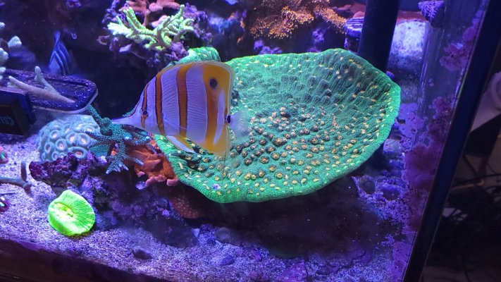
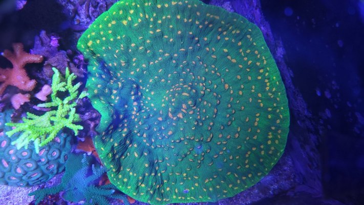
Awesome! Love this tank, that big raja rampage is my favorite piece
I Like it too, but it might be time to figure out how to strategically prune it back a bit. Its got to be at at least 10 to 12in across and showing no sings of slowing down.

I'm honestly not even sure how to frag this type of coral without ripping large section of the flesh of the skeleton?

Any tips?

20230514_092954.jpg 20230514_092932.jpg
 

Wiskey

Well-Known Member
View Badges
Joined
Sep 7, 2017
Messages
735
Reaction score
916
Rating - 0%
0   0   0
I also took this opportunity to use our new Multidapter in place of the threaded NPT fittings. This allow me to shave off nearly 3/4in off the total length of the RFG nozzle on the end of the elbow fitting.

You can see the difference in this pic between the old setup and the new - its a pretty significant amount

1683659489171.png
The tank looks fantastic, but that Multidapter is amazing!!! I've been waiting for fittings like this to come out specifically for areas were a perfect seal isn't important, but low profile is. Is that a glue in fitting? Or is it threaded and just setup so it doesn't tighten until it bottoms out?

Whiskey
 
OP
OP
Vivid Creative Aquatics

Vivid Creative Aquatics

Upgrade Your Flow!
View Badges
Joined
Oct 12, 2017
Messages
1,389
Reaction score
1,946
Location
Phoenix, AZ
Rating - 0%
0   0   0
The tank looks fantastic, but that Multidapter is amazing!!! I've been waiting for fittings like this to come out specifically for areas were a perfect seal isn't important, but low profile is. Is that a glue in fitting? Or is it threaded and just setup so it doesn't tighten until it bottoms out?

Whiskey
The Multidapter is made with same material we use for our new Flex-Sereis RFGs, so it like a stiff rubber like material. No glue or tape needed - it just snug-fits right in. The design is sort of like a stubby hose barb

This makes them highly compatible with all sort of pipes and bulkheads

And for bulkhead and pipe sockets (like on an PVC elbow)- it is the lowest profile modular hose connection you can get.

1684351291531.png
 
OP
OP
Vivid Creative Aquatics

Vivid Creative Aquatics

Upgrade Your Flow!
View Badges
Joined
Oct 12, 2017
Messages
1,389
Reaction score
1,946
Location
Phoenix, AZ
Rating - 0%
0   0   0
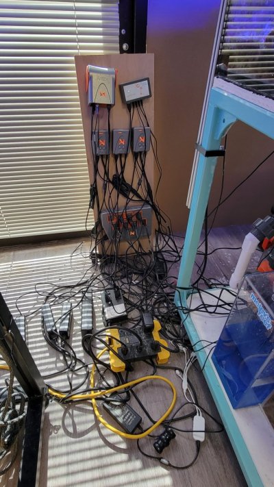
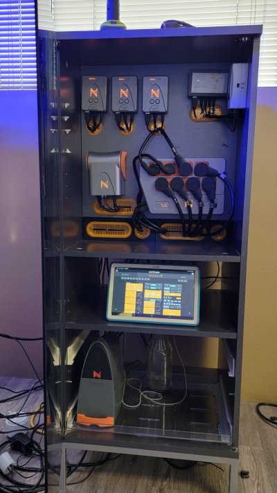
New Controller Cabinet!

Finally tackled the ever growing rats nest of wires that had been sitting behind the back corner of the tank, just out of site from the "pretty side" of the tank.

Honestly, it is kind of embarrassing how bad this got, but my guess we all have some aspect of our wiring we would like to fix.

Here what we started with

20230528_155758.jpg

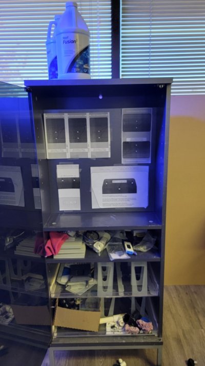
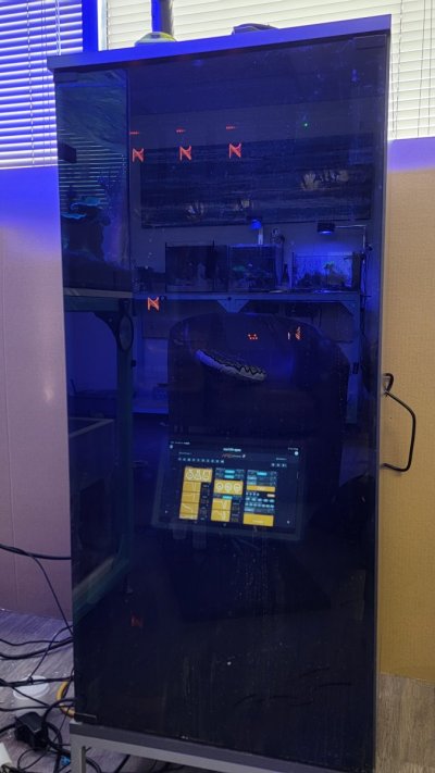
I secured an old Stereo Cabinet with a nice glass door. I actually picked it up over a year ago, and just never got to it. But i deiced with the long weekend I would get it done. I first started by repurposing one of the shelves to be the back wall .

I downloaded the Neptune Apex mounting templates from here

I then used those PDFs to plan the layout:
1685749590362.png


Then I printed and cut out the module shapes and taped up the back wall
20230528_131200.jpg


20230528_131340.jpg Made sure it would look good in the cabinet. All my junk is still in there - i had to clear that out too. Ugh

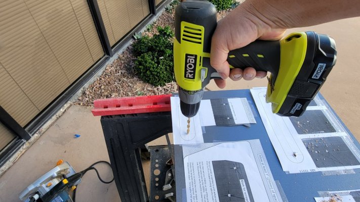
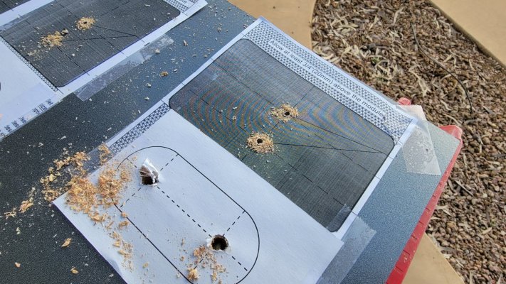
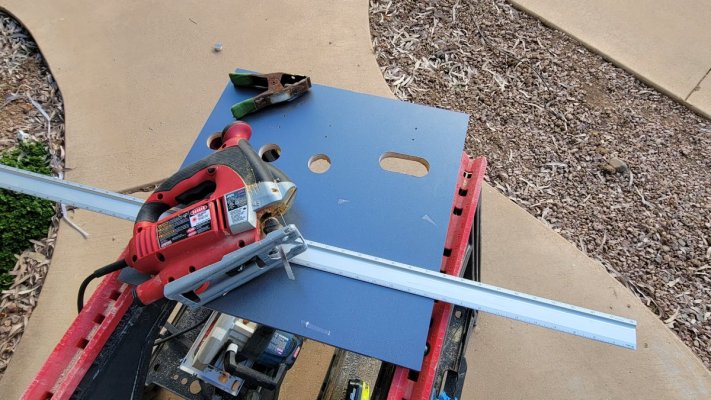
From there it was just a matter of drilling pilot hoes for the screws and cutting holes for the wires to pass throug, I used a 1.5in holesaw to cut the round holes and a the two end of each of the slot. I then used a jigsaw to cut the slots between the holes.

20230528_162403.jpg 20230528_162614.jpg 20230528_164413.jpg

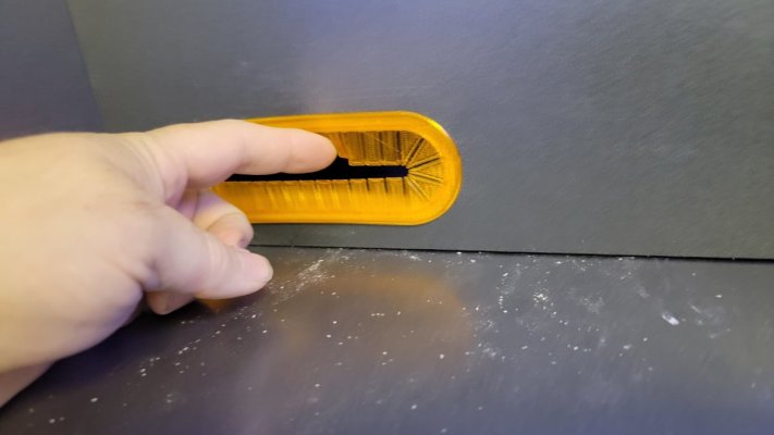
here is back wall with all the hole cut out - came out good, but not perfect, so I decide i needed some wire grommets. to clean up the look.

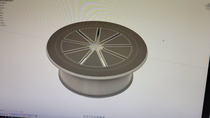
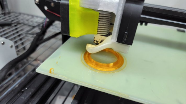
I figured, I own a few 3D printers :cool: , so i should just design an print my own

20230528_164857.jpg


20230528_180651.jpg 20230528_180204.jpg

I tried a few different styles and colors before settling on the final design in the middle

20230528_190744.jpg


20230529_140848.jpg I create some of the slots as well - these were done in TPU, so they are flexible


I also have to create a spacer for the bottom, since the overall size of the shelf I used was slightly short. I was originally going to keep it open, but i decided it didn't want to see the mess of wires that would be behind this wall.


This is the end result
20230530_084410.jpg


next, I needed some addition support for the back wall - so quickly draw up some corner brackets and printed off a batch. I had orange PETG loaded up on a free printed I just printed it in that color.
20230530_065704.jpg
20230530_084258.jpg


Now it was time to start wrangling the wires. The shear number of extension cords, aquabus cables and other wires is crazy. This is just just the first bundle. I ended up being a bundle that was near .5 to 3in in diameter

20230530_140506.jpg


Progress was slow, and it definitely got worse, before it started to get better

20230530_105401.jpg


The end result was very much worth the effort. I am pleased with the way it came out

20230530_165950.jpg 20230530_170001.jpg

20230601_194919.jpg
 
Last edited:
OP
OP
Vivid Creative Aquatics

Vivid Creative Aquatics

Upgrade Your Flow!
View Badges
Joined
Oct 12, 2017
Messages
1,389
Reaction score
1,946
Location
Phoenix, AZ
Rating - 0%
0   0   0
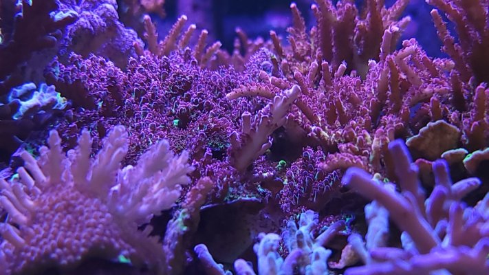
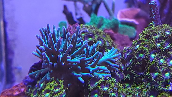
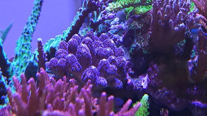
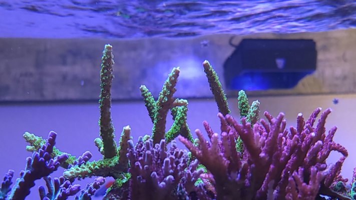
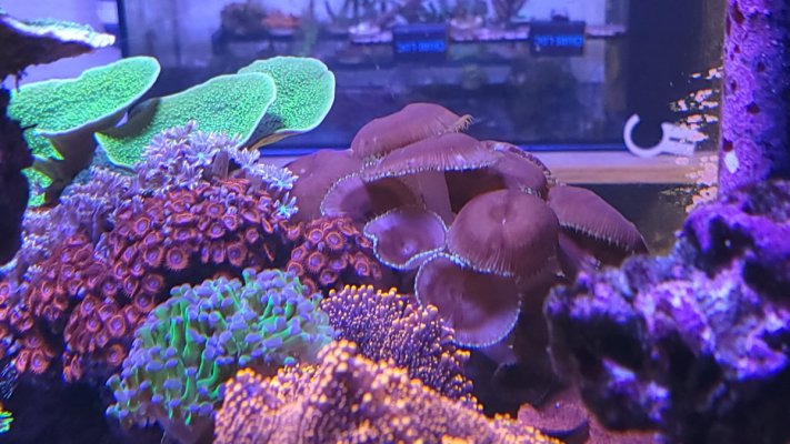
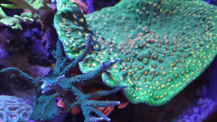
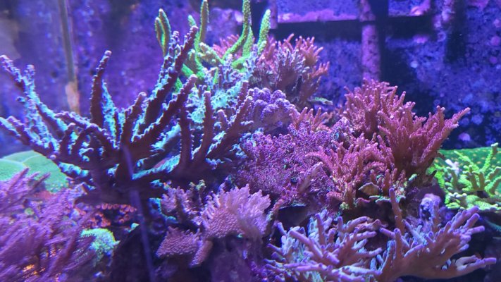
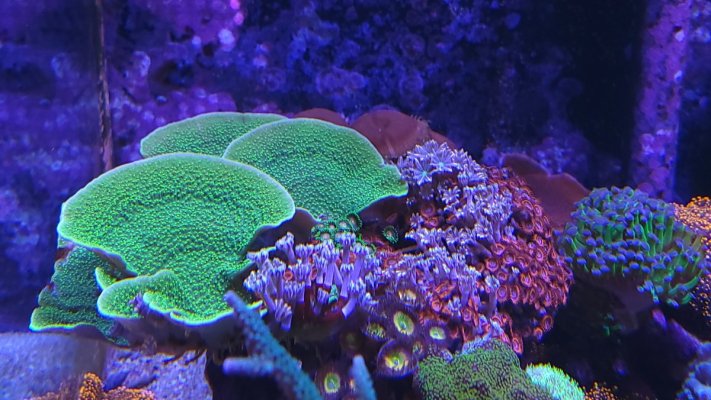
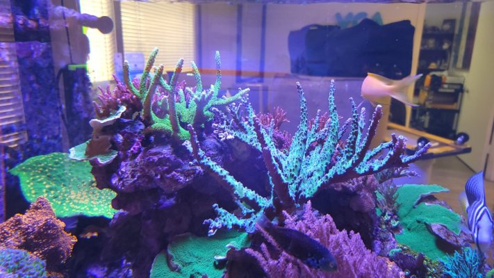
Just a photo bomb of the current growth in this tank - early on I decided to let this (as much as possible) grow in naturally, with very little intervention. meaning I would not prune/frag coral to keep them from touching. I wanted to see if they would stake out their territories and fight it out to make space for themselves.

So that didn't really come out as I had expected - it turns out , when coral are "happy", so to speak, they tend not to sting their neighbors. In fact, coral (both soft and Stoney) that you would think would sting each other are simply coexisting and growing together - almost mingling.

I personally have never experienced this in a tank I have grown out - usually, these coral would-be stinging and killing each other to make space.

20230808_160950.jpg
20230808_160514.jpg 20230808_160504.jpg 20230808_160422.jpg 20230808_160414.jpg


Check out this extreme example case - an SPS with a chalice just casually growing around it. Nether seem particularly bothered by the other

20230808_160358.jpg 20230808_160346.jpg 20230808_160322.jpg 20230808_160309.jpg


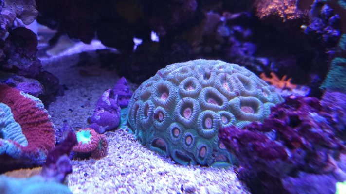
This is one of my favorite coral I own - It sits alone. Don't want to risk it with this one. I have had this one for at least 7 years, but it didn't really start growing until it went into this tank about two years ago. It has more then tripped in size since going into this tank. its got to be at at least 8 inches round
20230808_160242.jpg
 

Duzzy

Active Member
View Badges
Joined
May 20, 2020
Messages
182
Reaction score
96
Rating - 0%
0   0   0
IMG_20210427_123545_027.jpg The VCA 134-Gallon Cube - Random Flow Generator Powered Mixed Reef!

The first of two new offices tanks are officially under way, and I can’t wait to share it here on Reef-2-Reef

Our goal with this tank is to build a mixed reef tank with a unique flow solution that utilizes just Random Flow Generator® Nozzles to flow the entire tank.

Here are the initial details:

The Display Tank – 134 Gallons
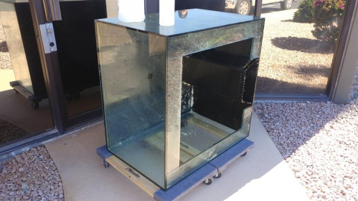
The Display Tank started out as a used Lemar 34x34x24 cube tank that we acquired from a local hobbyist - why build brand new when you can recycle – right?

The original configuration had the center overflow positioned on the back wall, with the standard three holes drilled in the bottom – two 1in holes for return lines and a single 1.5in hole for the drain.

The first task was to remove the back overflow box and prep the existing holes for the closed loop.

20210221_124650.jpg 20210324_110259.jpg

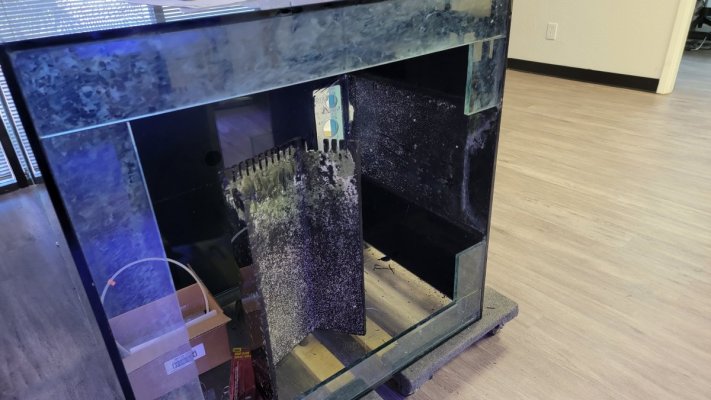
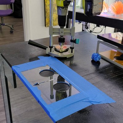
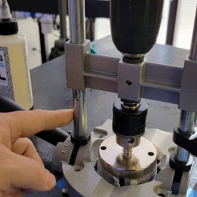
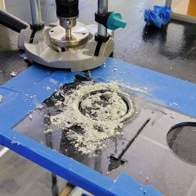
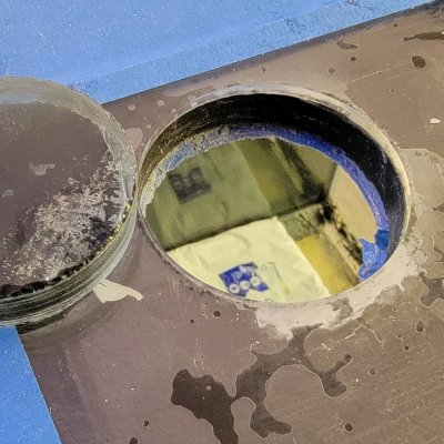
Next – we needed to drill 4 new holes – two for the returns and two for the EShopps Eclipse Overflow box. We did not have a way of running a continuous flow of water over the drill bit, without making a huge mess in the front lobby, so we use Glass Cutting Oil. Worked well. The process made some free sand. It if were not for the oil, I probably could have used it in a small nano tank.


IMG_20210423_095813_781.jpg IMG_20210423_095813_805.jpg IMG_20210423_095813_830.jpg IMG_20210423_095813_845.jpg


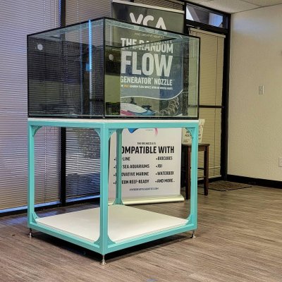
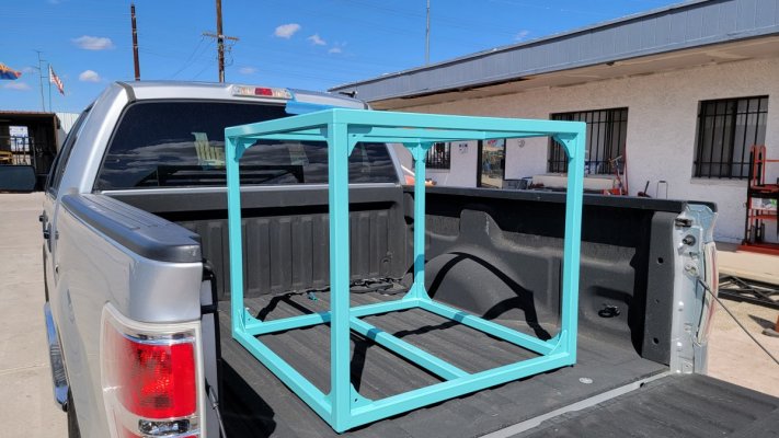
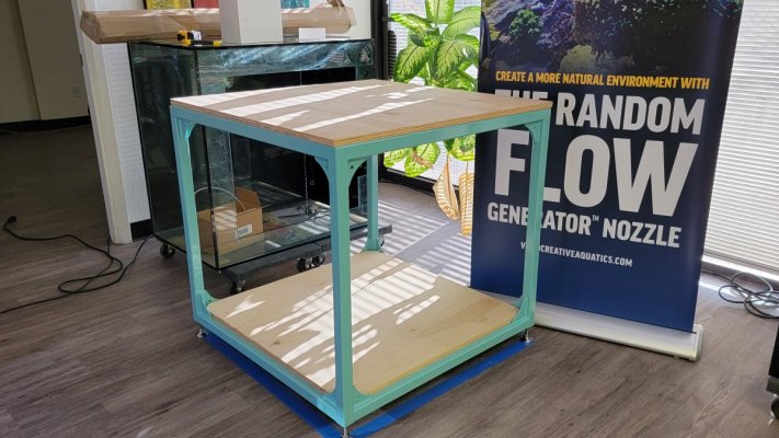
20210316_140223.jpg The Custom Steel Stand

The stand is a custom steel stand constructed out of 1 1/2" tube steel with 3/8 inch wall thickness. It’s pretty heavy duty, while still maintaining a minimalist appearance. We had it powder coated with an Aqua Blue gloss finish.


20210317_170903.jpg 20210316_145514.jpg

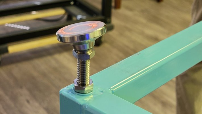
We added a 3/4in Burch plywood base and platform. The floor in tour office suite is severely uneven. You can see it, but it because very obvious when you try and level a tank. So I designed the stand to use heavy duty leveling feet.


The first Challenge - the size of the tank vs the size of the door
One of the first challenges with this tank was the physical size of the tank in relationship to the size of the front door to our office. The maximum door width is 32 inches wide. The tank came in on its side with no problem. However, the stand had a limitation of 32 inches as a max dimension. As a result, the stand is a little shorter than I would have liked.

The height of the steel stand is 32 inches. The adjustable feet add another 3 inches to the overall height. The final height of the stand is 35in. Add to that the 3/4in birch board used as the base under the tank and the top of the tanks sits just shy of 60in tall.
20210427_120104.jpg


The Dual Closed Loop - with Shared Drain

This build features a dual closed loop with shared drain. This will provide most of the flow in this tank and will be created using two of our 1in RFGS100LL Random Flow Generators®

This proved to be the second major challenge. The original design was to have the pumps mounted underneath the tank, upside down and out of the way. However, the sheer size of some of the plumbing fittings such as 1 1/2in elbows and Union Ball Valves made that nearly impossible.

The second challenge was being able to supply both pumps from a single drain. The drain is 1 1/2 inches which is more than enough for a single pump, but may be a bit restrictive for dual pumps. The biggest issue was friction caused by high velocity of flow through this pipe which could then lead to cavitation as the two pumps worked against one another for supply. To get around that and to minimize friction, we needed to reduce the velocity through the pipe.

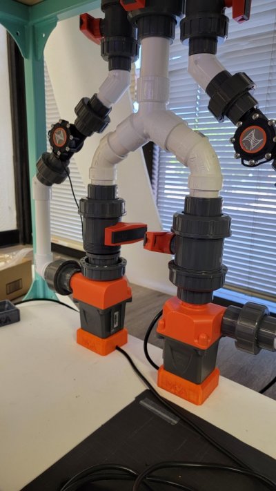
With the help of friend who knows more than I do about friction and flow, we came up with this design that uses a 60 degree 3-way Y to split the drain and create two separate runs leading to each pump. This effectively reduces the velocity in the sections leading to the pumps and minimizes the chances of starving either of the pumps.

20210705_174330.jpg


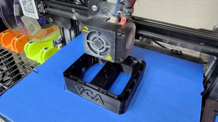
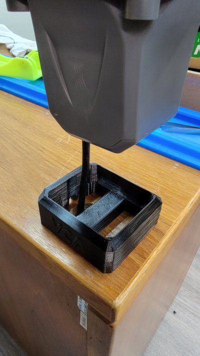
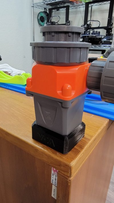
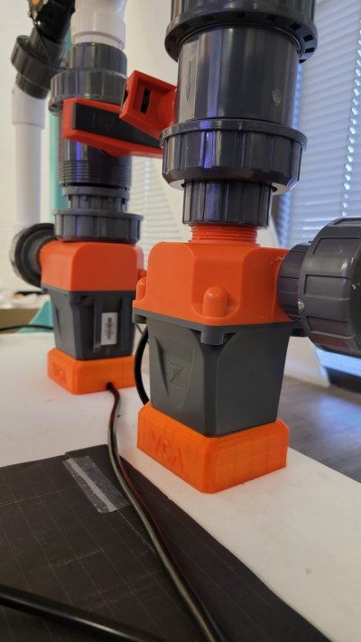
I mounted the pumps vertically to facilitate better flow into the inlet, but that presented a challenge. We didn't want to leave them dangling and unsupported. So, I designed and 3D printed these bases. The base helps to support the pumps and secure it in place. it also take stress off the plumbing. Once everything is done, I'll drill a hole underneath them and rout the wires underneath the platform so they are out of site.


20210705_130839.jpg

20210705_134824.jpg 20210705_134816.jpg 20210707_112122.jpg 20210707_112128.jpg


In our initial testing, the dual closed loop with shared drain design seems to work quite well. Both pumps can be run at 100% without any apparent issue. We’ll share some flow numbers once we get the Apex hooked up. Here are some videos of the iniitial flow testing.


The Flow Plan
The primary flow will be handled with this dual close loop. Each side of the loop is powered by its own Cor20 return pump. These will then be controlled through a Neptune Apex to vary the speed of each loop. The plan here is to slowly alternate the power between the two pumps at opposite intervals. So for instance over the 12 hour period the left pump will ramp from 80% down to 20%, while the right side will ramp up from 20% to 80%.

1626829967033.png


This will hopefully create a sort of switching dominate current inside the tank. At the peak while the left side is at 80% and the right side is at 20%, the dominant current will be going in a general clockwise direction around the tank. Mid-day will be 50% power on both loops, so just chaotic randomized motion. Then towards the end of the day, the general flow direction will switch to a counter-clockwise direction.

A Reverse Check Valve Design
Returns are going to be kind of interesting because we want to feature another unique setup here a swell. We needed a way to run a undersized sump, and still be able to drop the return lines well below the water line without fear of back siphon and an overflow. Every 1 inch of water level in the display tank is approx 5 gallons of water. So we drew inspiration from Marc Levinson of Melev's reef reverse check valve design.

Reverse check valve is interesting because it will break the siphon almost instantly when power is cut to the return pump. But you need to configure it correctly to work. Basicly the main lien that feed the two returns needed to be ABOVE the returns, and the valve needs to be either inline or above that. Here's what i have planned:

1626830131868.png


Basically, you place a check valve in reverse at the highest point within your plumbing. Pressure from the return pump presses on the check valve and closes it allowing water to then be routed to the return line.

When power to the pumps is cut, the pressure releases and allows the check valve to then open. Once the valve opens, it draws in air and breaks the siphon.

This will allow me to accomplish the two things i needed

First I'll be able to drop the return lines, which will also have RFG nozzles as far below the waterline as I like.

Second it would allow me to run a slightly undersized sump, giving me more room for other equipment underneath the tank. This is important because a cube set up is generally a little more difficult to deal with than your more common rectangular setup in terms of placing equipment.


Stay Tuned
So that's where we're at so far. The tank sits at about 3/4 of the way full of water as we test the closed loops. Comment below and let me know what you think . And stay tuned as we progress with this build. Next up is the sump design
Hi there, I was just watching a YouTube vid of you guys wasn’t aware that you were the same ppl.

The closed loop above am I to understand that system I could put a uv on each line of the closed loop and run the pumps at 2 different speeds? Also is the water coming straight from tank or via another hole in the the overflow box? I ask because I’m struggling to get my head around the closed loop.

great Build btw

Regards Duzzy
 

Duzzy

Active Member
View Badges
Joined
May 20, 2020
Messages
182
Reaction score
96
Rating - 0%
0   0   0
I've always been curious about it as well - and finally had an opportunity to do one.

Cant wait to actually test it out. I think the biggest challenge will be maintenance on the valve, and making sure algae doesn't grown inside and cause it to fail.

I plan on designing and and 3D printing a snap-on cover for the valve, to help block light from getting in.

1626885929165.png
Im not sure I understand what the reverse check does in a closed loop or why it’s even needed.
 

Duzzy

Active Member
View Badges
Joined
May 20, 2020
Messages
182
Reaction score
96
Rating - 0%
0   0   0
Plumbing is in full swing - I'll post some Pics later this week, once I have more of it done.

But- I thought I should share this first .

I need some support for the plumbing and could not find an adjustable solution that also looked good. So, I designed some adjustable-length pipe hangers.

They give me a adjustable length range of 1in to almost 2 inches, which is plenty to get around the beams on the stand.

1629669520032.png


1629669530377.png


1629669543840.png


I showed these on FB as well, and a number of people expressed interest in these, and a few of the other pieces and parts I have been creating for this build. So, I have created a new section off our website called "Early Access and Product R&D". I'll add thing such as this item to the catalog. If you need a set of these in either 1in or 1.25in you'll find them, here:


Brillian!
 

revhtree

Owner Administrator
View Badges
Joined
May 8, 2006
Messages
47,994
Reaction score
89,007
Rating - 100%
1   0   0
Crazy awesome job all around!
 
OP
OP
Vivid Creative Aquatics

Vivid Creative Aquatics

Upgrade Your Flow!
View Badges
Joined
Oct 12, 2017
Messages
1,389
Reaction score
1,946
Location
Phoenix, AZ
Rating - 0%
0   0   0
Hi there, I was just watching a YouTube vid of you guys wasn’t aware that you were the same ppl.

The closed loop above am I to understand that system I could put a uv on each line of the closed loop and run the pumps at 2 different speeds? Also is the water coming straight from tank or via another hole in the the overflow box? I ask because I’m struggling to get my head around the closed loop.

great Build btw

Regards Duzzy

The closed loops are separate form the returns. In our setup, we are running a dual closed loop with a shared drain. its a little unusually, but it was a way of utilizing the existing 3 holes on the bottom of this tank.

This is the photos of the dual the closed loop - pink arrows represent is water coming from an internal drain (1.25in PVC) inside the display tank. The blue arrows represent flow returning to the tank (1in PVC pipe), where they each drive a single 1in Random Flow Generator

1692735426211.png


Im not sure I understand what the reverse check does in a closed loop or why it’s even needed.
The Reverse Check Valve setup is part of the return line system - it is unrelated to the the closed loop

The return line is fed by its own pump that draws water from the sump and send it back to the display tank. By definition it is an "Open loop", as opposed to a closed loop.

The Reverse check valve allows me to run the return lines deep under the water line without worrying about draining to much back to the sump in the event the power is cut to the tank (like during water changes or power outages). Too much water to the sump could over flow the sump. Also since in a Reverse Check valve setup, it puts the default position of the valve as closed - there's no worries that it will fail when you need it most. It has worked quite well for 2 years now with zero maintenance needed on the valve.

1692735967160.png
 
Last edited:

Duzzy

Active Member
View Badges
Joined
May 20, 2020
Messages
182
Reaction score
96
Rating - 0%
0   0   0
The closed loops are separate form the returns. In our setup, we are running a dual closed loop with a shared drain. its a little unusually, but it was a way of utilizing the existing 3 holes on the bottom of this tank.

This is the photos of the dual the closed loop - pink arrows represent is water coming from an internal drain (1.25in PVC) inside the display tank. The blue arrows represent flow returning to the tank (1in PVC pipe), where they each drive a single 1in Random Flow Generator

1692735426211.png


The Reverse Check Valve setup is part of the return line system - it is unrelated to the the closed loop

The return line is fed by its; own pump that draws water from the sump and send it back to the display tank. By definition it is a "Open loop", as opposed to a closed loop.

The Reverse check valve allows be to run the return lines deep under the water line without worrying about draining to much back to the sump in the event the power is cut to the tank (like during water changes or power outages). Too much water to the sump could over flow the sump. Also, since in a Reverse Check valve setup puts the default position of the valve is closed - there's no worries that it will fail when you need it most. It has worked quite well for 2 years now with zero maintenance needed on the valve.

1692735967160.png
Oh ok same principle as tge siphon break on a durso or herbie. It’s a great desigun and something to model except my water will be run in the light cabinet above tank. I’m searching for light blue return nozzles and light blue even clear return nozzle’s to try and hide it as best I can. Not that I’ve seen clear except in freshwater and I don’t want to use glass
 
OP
OP
Vivid Creative Aquatics

Vivid Creative Aquatics

Upgrade Your Flow!
View Badges
Joined
Oct 12, 2017
Messages
1,389
Reaction score
1,946
Location
Phoenix, AZ
Rating - 0%
0   0   0
Oh ok same principle as tge siphon break on a durso or herbie. It’s a great desigun and something to model except my water will be run in the light cabinet above tank. I’m searching for light blue return nozzles and light blue even clear return nozzle’s to try and hide it as best I can. Not that I’ve seen clear except in freshwater and I don’t want to use glass
If its going into a reef tank - no matte the color (or lack there off), it will evenly turn purple with coral algae algae growth. :)

The Random Flow Generator is offered in Black - the easiest color to maintain in a reef tank.
 

Duzzy

Active Member
View Badges
Joined
May 20, 2020
Messages
182
Reaction score
96
Rating - 0%
0   0   0
If its going into a reef tank - no matte the color (or lack there off), it will evenly turn purple with coral algae algae growth. :)

The Random Flow Generator is offered in Black - the easiest color to maintain in a reef tank.
I know and going purple it may hide it better
 
OP
OP
Vivid Creative Aquatics

Vivid Creative Aquatics

Upgrade Your Flow!
View Badges
Joined
Oct 12, 2017
Messages
1,389
Reaction score
1,946
Location
Phoenix, AZ
Rating - 0%
0   0   0
Just a recent top-down photo showing the scale of that chalice in the back.

That chalice in the back corner is nearly 1/4 of the total tank footprint now. I think I need to find a way to trim that down a bit.


20230817_182830.jpg


as far as I can tell, its not actually encrusted on the the rock but rather just laying over it However it is giving that blue-green acro a big hug, and I'll have to frag the acro to get it out

20230808_160358.jpg


the original frag plug it cam in on was secured to a rock that was not part of the original aqua scape, so it should lift right out.

What do you think - should i take it out, cut off ab out 3 or 4 inches of the out disc and put it back? or is there a better way? Or - should I just leave it along and let it grow as it wants too
 

CBonito

Valuable Member
View Badges
Joined
Aug 20, 2023
Messages
1,114
Reaction score
1,303
Location
Detroit Area
Rating - 0%
0   0   0
Plumbing is in full swing - I'll post some Pics later this week, once I have more of it done.

But- I thought I should share this first .

I need some support for the plumbing and could not find an adjustable solution that also looked good. So, I designed some adjustable-length pipe hangers.

They give me a adjustable length range of 1in to almost 2 inches, which is plenty to get around the beams on the stand.

1629669520032.png


1629669530377.png


1629669543840.png


I showed these on FB as well, and a number of people expressed interest in these, and a few of the other pieces and parts I have been creating for this build. So, I have created a new section off our website called "Early Access and Product R&D". I'll add thing such as this item to the catalog. If you need a set of these in either 1in or 1.25in you'll find them, here:


They got my interest! I ordered a couple pair of them. Thanks for making these. They look great!

I have a couple of your flow kits too and didnt even realize!
 

Freshwater filter only or is it? Have you ever used an HOB filter on a saltwater tank?

  • I currently use a HOB filter on my reef tank.

    Votes: 31 28.4%
  • I don’t currently use a HOB filter on my reef tank, but I have in the past.

    Votes: 20 18.3%
  • I have used a HOB on fish only or quarantine tanks, but not on the display tank.

    Votes: 28 25.7%
  • I have never used a HOB on a saltwater tank.

    Votes: 28 25.7%
  • Other.

    Votes: 2 1.8%
Back
Top