reef-pi :: An opensource reef tank controller based on Raspberry Pi.

OP
OP
Ranjib

Ranjib

7500 Club Member
View Badges
Joined
Apr 16, 2016
Messages
9,846
Reaction score
17,069
Location
Pleasant Hill, Concord
Rating - 0%
0   0   0
I am totally lost with the e-mail alerts. I thought i had set it up correctly but apparently not. is there a link to tutorial.
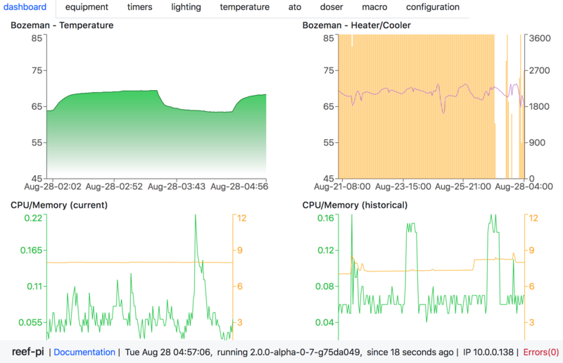
Check out the alert section
 

Broady2067

Community Member
View Badges
Joined
Jun 21, 2023
Messages
99
Reaction score
87
Location
Sheffield. UK
Rating - 0%
0   0   0

Check out the alert section
Hi Ranjib. I have tried to follow this but no luck as yet.
 

yury88

Active Member
View Badges
Joined
Oct 21, 2023
Messages
191
Reaction score
134
Location
indo-pacific
Rating - 0%
0   0   0
That’s is very different than saying reef-pi has no api. Drivers have specifics (like i2c protocol) that’s very different across .. hence driver types are fixed. There’s file based driver that you can use to integrate arbitrary devices
This will require creating a service for each device on linux based platform.
Not easy for users. Easier to upgrade reef-pi code by adding universal protocol with template supported. MQTT and REST API
 

iamdan

Community Member
View Badges
Joined
Jul 1, 2022
Messages
62
Reaction score
61
Location
Western Australia
Rating - 0%
0   0   0
Hi All

Was hoping i could get some guidance / verification / sanity check that i have done things right as reading various posts and articles on the matter has got me quite confused lol.

I have setup a standard Raspberry Pi 4 with "Bullseye Lite" and the only thing connected to it is an Atlas Ph Module and Atlas Ph Isolation Board and it is wired directly to the Raspberry Pi GPIO Pins.

It is this type:
1713492252068.png

To connect the pH probe i have the connector that converts the connector on the Isolation Board to "BNC"

I have gone through the process documented by Atlas to get the pH Circuit to communicate in i2c mode fine and the Raspberry Pi with i2cdetect / reef-pi detects and communicates with the pH Circuit. Also it is connected to the 3.3v line on the Raspberry Pi.

The Isolation Board's datasheet: https://files.atlas-scientific.com/electrically-isolated-ezo-carrier-board.pdf states that it already has pull-up resistors and what not:
1713492615276.png


So my questions are:
1.
I am assuming that i don't need to connect any resistors or whatever to the lines before they connect into the GPIO pins as per some articles online to do with pH modules?

2. In my config.txt i have the following set:
dtparam=i2c_arm=on
#dtparam=i2c_arm_baudrate=10000
dtoverlay=pwm-2chan
#dtparam=i2s=on
dtparam=spi=off

Wether or not i enable or disable dtparam=i2c_arm_baudrate=10000 and reboot, I can still see the sensor by i2cdetect and in reef-pi and monitoring it over a few hour period of either having this enabled or disabled i am not registering any drops.

Atlas instructions from what i can see unless i am blind don't mention any setting of Raspberry Pi i2c baudrate so assuming leaving it disabled will be ok?

3. I understand this pH circuit can be calibrated directly outside of reef-pi however is it still ok to perform calibration inside of reef-pi using reef-pi's ui calibration tool?

Apologies for the long post, just wanted to cover all the bases in one post that i could think of, if this requires to be posted to a separate thread i am more than happy to copy it to one and delete it from here.

Daniel
 

Barclay

New Member
View Badges
Joined
Jan 9, 2014
Messages
15
Reaction score
6
Location
Potenza Italy
Rating - 0%
0   0   0
Hi all friends, I have been using a reef-pi controller for several years, I use it for ATO, dosers, temperature and low voltage electrical users.
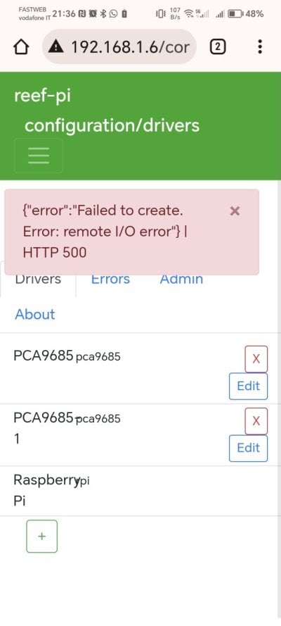
today I wanted to use a ph probe with ASD11115 but if I try to add the driver I get this error. Can any of you help me solve this problem? If I try to add other drivers everything works correctly, thanks in advance (goo.... translate)
 

Attachments

  • Screenshot_20240421_213623.jpg
    Screenshot_20240421_213623.jpg
    60.9 KB · Views: 18

BenB

Active Member
View Badges
Joined
Jun 11, 2019
Messages
100
Reaction score
152
Rating - 0%
0   0   0
Hi Barclay, what is de adress you entered when creating the driver in reef pi? The ADS1115 default I2C Address is 0x48 (Hex). In decimal that will be 72.
 

BenB

Active Member
View Badges
Joined
Jun 11, 2019
Messages
100
Reaction score
152
Rating - 0%
0   0   0
Hi all friends, I have been using a reef-pi controller for several years, I use it for ATO, dosers, temperature and low voltage electrical users.
today I wanted to use a ph probe with ASD11115 but if I try to add the driver I get this error. Can any of you help me solve this problem? If I try to add other drivers everything works correctly, thanks in advance (goo.... translate)
Adding analog sensors with ADS1115

Michael Lane has been working on a new ADS1015/ADS1115 driver for reef-pi.

This brings new possibilities to Reef-Pi:
  • PH/Orp probes
  • Pressure sensors
  • Flow sensors
  • Etc.
Any analog sensor can be used as long as the analog signal is in between 2.0V to 5.5V.

ADS1115 16-Bit ADC - 4 Channel with Programmable Gain Amplifier

ADS1115.png


ADS1115 Features:
  • Resolution: 16 Bits
  • Programmable Sample Rate: 8 to 860 Samples/Second
  • Power Supply/Logic Levels: 2.0V to 5.5V
  • Low Current Consumption: Continuous Mode: Only 150µA Single-Shot Mode: Auto Shut-Down
  • Internal Low-Drift Voltage Reference
  • Internal Oscillator
  • Internal PGA: up to x16
  • I2C Interface: 4-Pin-Selectable Addresses
  • Four Single-Ended or 2 Differential Inputs
  • Programmable Comparator
I had an ADS1115 board so I tried if my PH probe is working. So I made a “How to guide” maybe it will be of use for others. I used a Raspberry Pi 2 Model B with Reef-Pi version 3.5.

Add driver under Configuration/Drivers
1.png


Configure the Driver:
2.png

Name: PH
Type: ads1115
Address: standard is 72
Gain: 2/3, 1, 2, 4, 8 or 16

An Adafruit tutorial has this guidance.
# Choose a gain of 1 for reading voltages from 0 to 4.09V.
# Or pick a different gain to change the range of voltages that are read:
# - 2/3 = +/-6.144V (High Gain, Sensitive to noise)
# - 1 = +/-4.096V
# - 2 = +/-2.048V
# - 4 = +/-1.024V
# - 8 = +/-0.512V
# - 16 = +/-0.256V (Low Gain, Not Sensitive to Noise)
# See table 3 in the ADS1015/ADS1115 datasheet for more info on gain.

Reboot (Configuration/Admin)

Add analog input under Configuration/Connectors
3.png


Configure the connector
4.png

Name: PHpin0
Pins: 0 (depends what pin you use on the ADS1115 board)
Driver: PH
Reload (Configuration/Admin)

Add the probe under pH
5.png


Configure the PH probe
6.png

Name: PH
Analog input: PHpin0
Check frequency: 10
Ph status: Enabled
The other settings are not mandatory.

Calibration
The first readings will be high:
7.png

Therefore you need to calibrate!

To be able to calibrate you first have to disable the Ph status
  • Edit ph.
  • Disable probe.
  • Save
  • Calibrate
  • Rinse probe in rodi
  • Place in 7 calibration fluid
  • Wait for readings to stabilize
  • Set cal value to 7 (Midpoint)
  • Push Run
  • Rinse probe
  • Put in 10 calibration fluid
  • Set cal value to 10 (Second Point)
  • Run
  • Enable probe
  • Rinse probe and check both 7 and 10 and make sure it’s close.
Enjoy!
 

dmsc2fs

Active Member
View Badges
Joined
Dec 29, 2021
Messages
455
Reaction score
546
Location
Charleston
Rating - 0%
0   0   0
If I didn't miss anything, the last time Salinity and ORP probes came up is around 2017. Has anything changed with being able to add any new probes?
 

Simonv92

Active Member
View Badges
Joined
Oct 21, 2014
Messages
128
Reaction score
100
Location
Italy
Rating - 0%
0   0   0
Hi All! I'm working again on my Reef-Pi build. I'm testing a custom led driver to power my GNC Bluray M PRO using Reef-pi instead of the AirLink.
The original control allow me to use the blue channel at 1% as moon light and it produces a very dim blue light.
Using Reef-Pi if I set the dim to 1% it is much more brighter, it seems that it isn't using the 12bit capabilities of the PCA9685. How can I solve that?
Thank you very much!
Simone
 

elysics

Valuable Member
View Badges
Joined
Jan 15, 2020
Messages
1,526
Reaction score
1,515
Rating - 0%
0   0   0
Hi All! I'm working again on my Reef-Pi build. I'm testing a custom led driver to power my GNC Bluray M PRO using Reef-pi instead of the AirLink.
The original control allow me to use the blue channel at 1% as moon light and it produces a very dim blue light.
Using Reef-Pi if I set the dim to 1% it is much more brighter, it seems that it isn't using the 12bit capabilities of the PCA9685. How can I solve that?
Thank you very much!
Simone
Do you know if the original controller uses pwm signals in the first place? Or maybe true 0-10V (analog voltage, not pwm). The PCA9685 does something around 3.3V pwm or 5V pwm, what circuit did you create to convert it to whatever signal the lamp/ldriver expects, that circuit could mess with the signal as well.

Id first look at the output with a multimeter, then if you have it with an oscilloscope or logic analyzer, to see what's actually happening.
 

oreo54

5000 Club Member
View Badges
Joined
Sep 18, 2017
Messages
5,662
Reaction score
3,490
Rating - 0%
0   0   0
Hi All! I'm working again on my Reef-Pi build. I'm testing a custom led driver to power my GNC Bluray M PRO using Reef-pi instead of the AirLink.
The original control allow me to use the blue channel at 1% as moon light and it produces a very dim blue light.
Using Reef-Pi if I set the dim to 1% it is much more brighter, it seems that it isn't using the 12bit capabilities of the PCA9685. How can I solve that?
Thank you very much!
Simone
There are "hints" here:
and fixed years ago?
Are you running old code?
 

Simonv92

Active Member
View Badges
Joined
Oct 21, 2014
Messages
128
Reaction score
100
Location
Italy
Rating - 0%
0   0   0
Thank both for the comments.
The original driver uses the same driver (LM3409HV)
On the original I've meauser with the oscilloscope a 5V 20KHz PWM signal on the control pin.
On my driver I've setup the frequency output of the PCA9685 at 1KHz and I'm feeding the signal directly into the dim pin.
I'm using the latest version (6.0) of Reef-Pi

First image is the PWM signal on the original AirLink set to "moon light":

SDS00001.png


Second is the signal coming out of the PCA9685 with Reef-Pi set to 1%:

SDS00002.png
 

oreo54

5000 Club Member
View Badges
Joined
Sep 18, 2017
Messages
5,662
Reaction score
3,490
Rating - 0%
0   0   0
Thank both for the comments.
The original driver uses the same driver (LM3409HV)
On the original I've meauser with the oscilloscope a 5V 20KHz PWM signal on the control pin.
On my driver I've setup the frequency output of the PCA9685 at 1KHz and I'm feeding the signal directly into the dim pin.
I'm using the latest version (6.0) of Reef-Pi

First image is the PWM signal on the original AirLink set to "moon light":

SDS00001.png


Second is the signal coming out of the PCA9685 with Reef-Pi set to 1%:

SDS00002.png
Well still beyond my pay grade but try changing the pwm frequency in reef-pi.
Just for fun.
Way back in my mind I "remember" something about a "relationship" between frequency and pwm stepping.
Its not "normal" so to speak.
Above is a bout a 1% chance I actually know what I'm talking about.. :)

As to frequency change:

Oh this maybe..
It turns out that Broadcom implemented "balanced" PWM in order to make the on and off PWM pulses as evenly distributed as possible. They give a description of the algorithm and some more discussion on page 139 of their datasheet:http://www.element14.com/community/servlet/JiveServlet/
Though that is err "backwards" from what I was thinking..

Anyways seems easy enough to change the frequency and see what happens.

Oh a "random" quote..
For PWM, the Pi's PWM output is by default not a typical mark:space waveform, but a balanced waveform, so it may not be what you're after - certianly the "frequency" becomes somewhat interesting to calculate, however you can put it into mark:space ratio mode then its more predictable, but it's still driven off the same 19.2MHz clock as above.

In the KHz and lower range, then you can generate reasonably accurate frequencies in software - look at the softTone module in wiringPi - it can generate a frequency from 0 to 5KHz - there is some jitter, but it's "good enough for jazz" ...


OR the onboard led drivers can't deal w/ such a low frequency as the 9685 is capable of..
And "if" I read the data sheet right max is :
PWM frequency PRE_SCALE
The hardware forces a minimum value that can be loaded into the PRE_SCALE register
at ‘3’. The PRE_SCALE register defines the frequency at which the outputs modulate. The
prescale value is determined with the formula shown in Equation 1:
(1)
where the update rate is the output modulation frequency required. For example, for an
output default frequency of 200 Hz with an oscillator clock frequency of 25 MHz:
(2)
The maximum PWM frequency is 1526 Hz if the PRE_SCALE register is set "0x03h".
The minimum PWM frequency is 24 Hz if the PRE_SCALE register is set "0xFFh".
The PRE_SCALE register can only be set when the SLEEP bit of MODE1 register is set to
logic 1.
Shouldn't be too hard to find the driver ic on the light.
 

Attachments

  • PCA9685[1].pdf
    399.2 KB · Views: 2
Last edited:

Simonv92

Active Member
View Badges
Joined
Oct 21, 2014
Messages
128
Reaction score
100
Location
Italy
Rating - 0%
0   0   0
Well still beyond my pay grade but try changing the pwm frequency in reef-pi.
Just for fun.
Way back in my mind I "remember" something about a "relationship" between frequency and pwm stepping.
Its not "normal" so to speak.
Above is a bout a 1% chance I actually know what I'm talking about.. :)

As to frequency change:

Oh this maybe..

Though that is err "backwards" from what I was thinking..

Anyways seems easy enough to change the frequency and see what happens.

Oh a "random" quote..


OR the onboard led drivers can't deal w/ such a low frequency as the 9685 is capable of..
And "if" I read the data sheet right max is :

Shouldn't be too hard to find the driver ic on the light.
I already try it.. max freq with the PCA9685 is 1.5KHz. I've tryed frequenzies from 100Hz to 1KHz with no luck..
 

Managing real reef risks: Do you pay attention to the dangers in your tank?

  • I pay a lot of attention to reef risks.

    Votes: 29 41.4%
  • I pay a bit of attention to reef risks.

    Votes: 23 32.9%
  • I pay minimal attention to reef risks.

    Votes: 12 17.1%
  • I pay no attention to reef risks.

    Votes: 5 7.1%
  • Other.

    Votes: 1 1.4%
Back
Top