Essential Power Bar - DIY Single PCB design with 3D printed case

OP
OP
theatrus

theatrus

Valuable Member
View Badges
Joined
Mar 26, 2016
Messages
1,959
Reaction score
3,356
Location
Sacramento, CA area
Rating - 0%
0   0   0
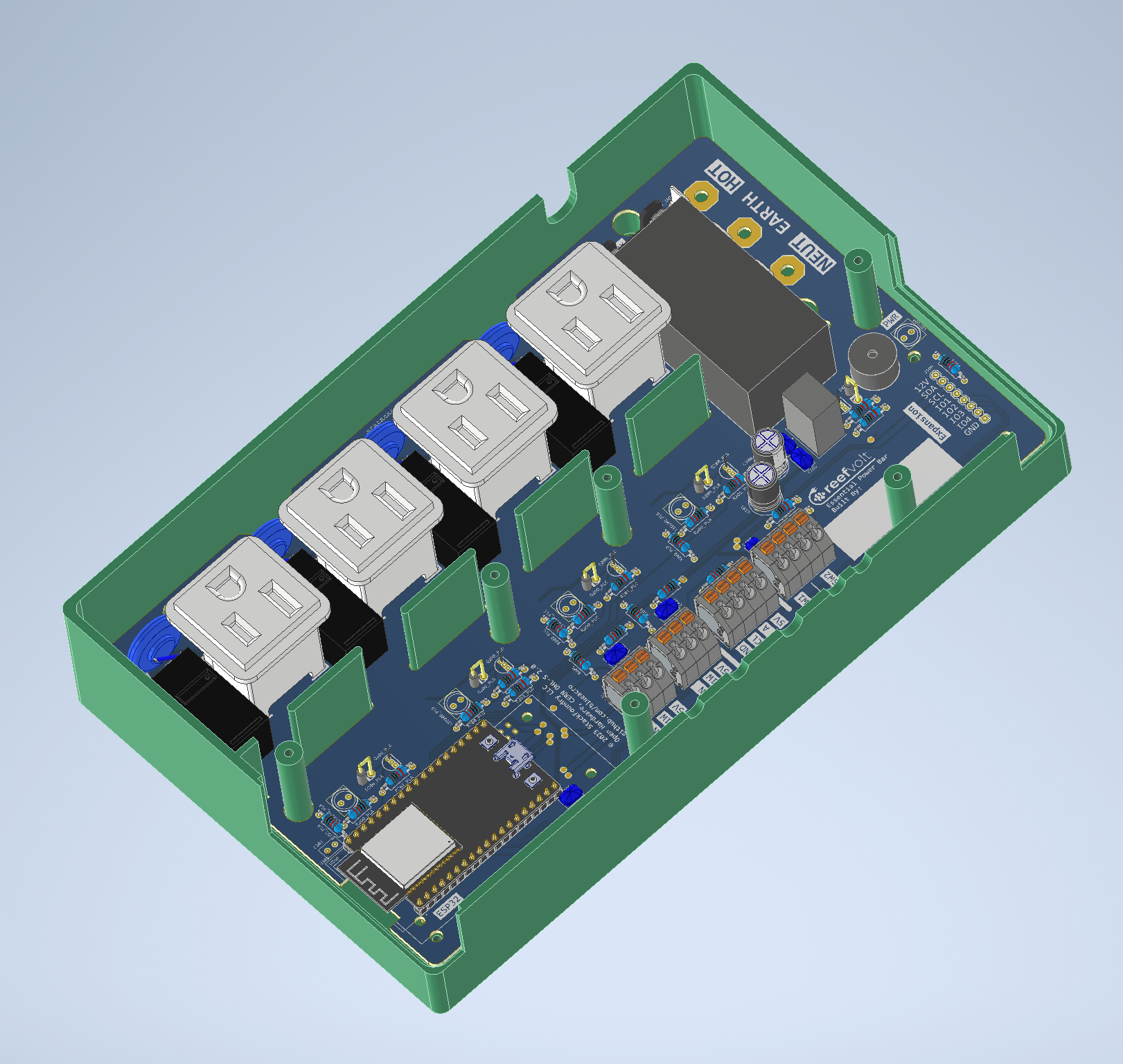
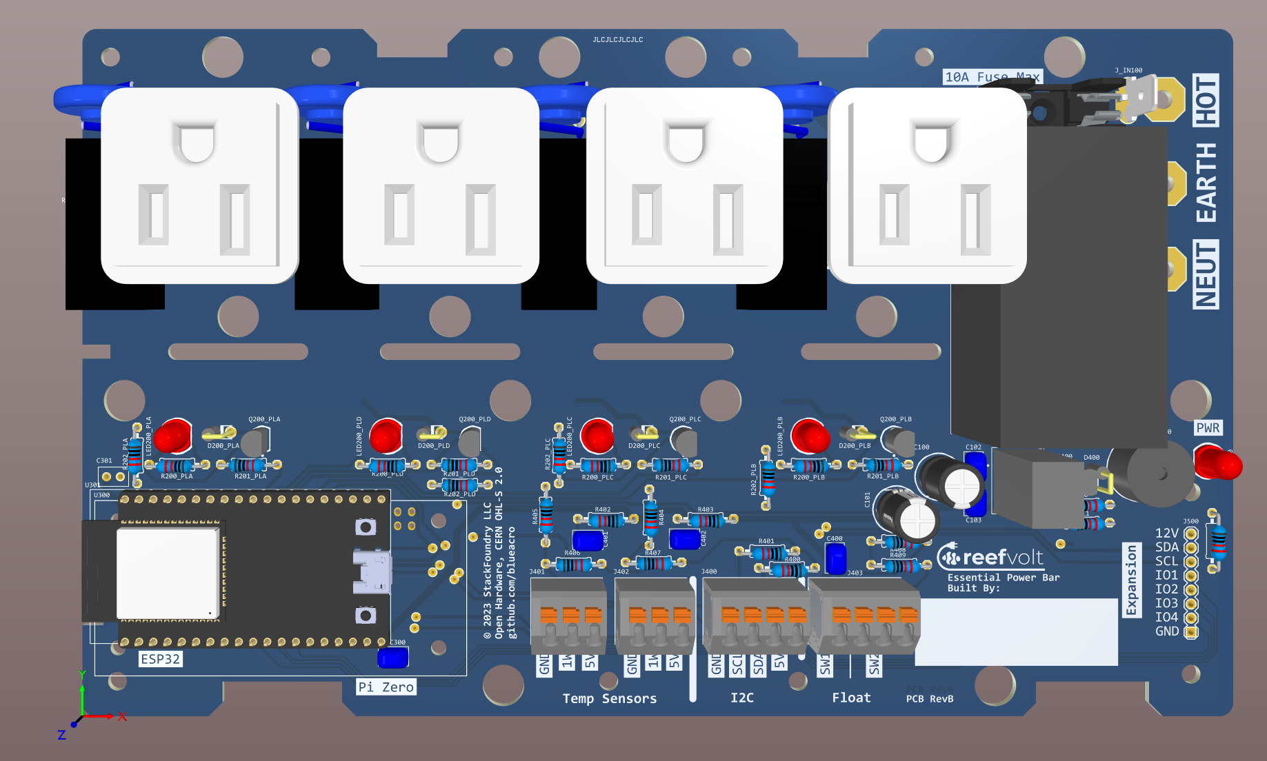
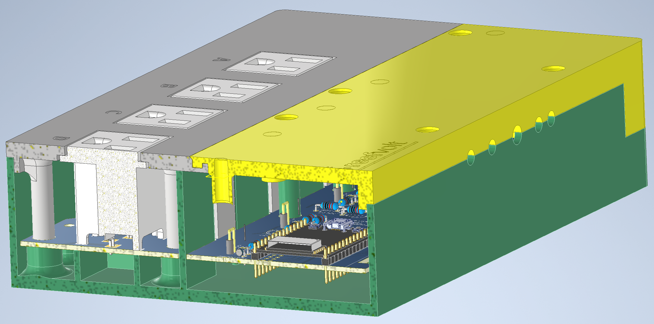
Some new design snapshots. Basically the same, except the relays nicely mesh under the outlets now. The low voltage parts aren't moved around, but the case bosses got some ergonomic adjustments:

build3.png


build4.png

build5.png
 
OP
OP
theatrus

theatrus

Valuable Member
View Badges
Joined
Mar 26, 2016
Messages
1,959
Reaction score
3,356
Location
Sacramento, CA area
Rating - 0%
0   0   0

Bio

New Member
View Badges
Joined
Sep 23, 2023
Messages
2
Reaction score
0
Location
usa
Rating - 0%
0   0   0
Great work im very interested in this using a esp32 it would mesh right into home assistant and node red for control and automation. Does it have power monitoring on the outlets that would be a great plus if it does or could be implemented in the design.
 
OP
OP
theatrus

theatrus

Valuable Member
View Badges
Joined
Mar 26, 2016
Messages
1,959
Reaction score
3,356
Location
Sacramento, CA area
Rating - 0%
0   0   0
Great work im very interested in this using a esp32 it would mesh right into home assistant and node red for control and automation. Does it have power monitoring on the outlets that would be a great plus if it does or could be implemented in the design.

Nothing built in for simplicity. Can be added. I had actually started down this route, at least for a central power meter (per port adds money if you don't want to roll our own integrators like Neptune did with the PSoCs), but that went past the "make it easy to make for people, avoid SMD" approach :)

Since I mixed the order with the more complicated DCBuddy board, it took a whole week to make and ship.
 

bishoptf

Valuable Member
View Badges
Joined
Jan 1, 2019
Messages
1,345
Reaction score
1,722
Location
Missouri
Rating - 0%
0   0   0
@theatrus I am in the need to replace one of my janky power strips but can I attach this via my normal reef-pi? I have 5v headers and IO ports coming off my hat and that is what I am using today but wasn't clear if I could do that with this build or not, probably a dumb question but thought I would ask, thanks.
 
OP
OP
theatrus

theatrus

Valuable Member
View Badges
Joined
Mar 26, 2016
Messages
1,959
Reaction score
3,356
Location
Sacramento, CA area
Rating - 0%
0   0   0
@theatrus I am in the need to replace one of my janky power strips but can I attach this via my normal reef-pi? I have 5v headers and IO ports coming off my hat and that is what I am using today but wasn't clear if I could do that with this build or not, probably a dumb question but thought I would ask, thanks.

You can - you can attach those GPIOs to the matching pins on the board, and just not attach an ESP32 or Reef-Pi. The relay power supply is all on board, so just the GPIOs and the GND pin would be needed.
 

bishoptf

Valuable Member
View Badges
Joined
Jan 1, 2019
Messages
1,345
Reaction score
1,722
Location
Missouri
Rating - 0%
0   0   0
You can - you can attach those GPIOs to the matching pins on the board, and just not attach an ESP32 or Reef-Pi. The relay power supply is all on board, so just the GPIOs and the GND pin would be needed.
So what is the input power wise, 12v? One more question what would it take to scale out to make a 8 outlet version. I know you made it for 3d print out but you could make a 2 piece print and just glue it together. I guess the other thing I could do is to make 2 of them and just use them separately. Guess i need to get looking at a parts list since the 5v relays i am using now appear to not always want to work, my other option is to go with another dj power strip.
 
OP
OP
theatrus

theatrus

Valuable Member
View Badges
Joined
Mar 26, 2016
Messages
1,959
Reaction score
3,356
Location
Sacramento, CA area
Rating - 0%
0   0   0
So what is the input power wise, 12v? One more question what would it take to scale out to make a 8 outlet version. I know you made it for 3d print out but you could make a 2 piece print and just glue it together. I guess the other thing I could do is to make 2 of them and just use them separately. Guess i need to get looking at a parts list since the 5v relays i am using now appear to not always want to work, my other option is to go with another dj power strip.

Its self powered - the AC/DC brick inside produces the 12V, and there is a regulator for 5V for powering logic (which won't be needed, though you could use externally or not attach the regulator).

Outside of the case its fairly straight forward to throw on more outlets (double row), just don't have the cycles to do that at the moment.

Parts list is on the last page of the PDF here: https://github.com/blueacro/reefvol...blob/main/pcb/pdf/schematics_bom_assembly.pdf

I hadn't gotten to the build guide :-D, but the PCB works for my use so far.

If you don't attach the Pi or ESP32, you can omit a lot of parts - the terminal blocks, buzzer, the circuits around 1wire, many of the ceramic caps. Basically any parts starting with 4xx and 3xx.
 

bishoptf

Valuable Member
View Badges
Joined
Jan 1, 2019
Messages
1,345
Reaction score
1,722
Location
Missouri
Rating - 0%
0   0   0
Its self powered - the AC/DC brick inside produces the 12V, and there is a regulator for 5V for powering logic (which won't be needed, though you could use externally or not attach the regulator).

Outside of the case its fairly straight forward to throw on more outlets (double row), just don't have the cycles to do that at the moment.

Parts list is on the last page of the PDF here: https://github.com/blueacro/reefvol...blob/main/pcb/pdf/schematics_bom_assembly.pdf

I hadn't gotten to the build guide :-D, but the PCB works for my use so far.

If you don't attach the Pi or ESP32, you can omit a lot of parts - the terminal blocks, buzzer, the circuits around 1wire, many of the ceramic caps. Basically any parts starting with 4xx and 3xx.
Nother dumb question could i bqck feed 12v through the expansion ports. I already have 12v and wondering if i skip the power supply and feed 12v from the expansion would that work for the relays?
 

yury88

Community Member
View Badges
Joined
Oct 21, 2023
Messages
93
Reaction score
69
Location
indo-pacific
Rating - 0%
0   0   0
I like the project, but in my point of view electronic shouldn't use 70% of space. It's because you decided to go with multiple jacks for peripherals. Look on mass production smart power bars- they are thin and utilizing space for 100%
For me- I just can't fit so huge box for just 4 outlets
 
OP
OP
theatrus

theatrus

Valuable Member
View Badges
Joined
Mar 26, 2016
Messages
1,959
Reaction score
3,356
Location
Sacramento, CA area
Rating - 0%
0   0   0
I like the project, but in my point of view electronic shouldn't use 70% of space. It's because you decided to go with multiple jacks for peripherals. Look on mass production smart power bars- they are thin and utilizing space for 100%
For me- I just can't fit so huge box for just 4 outlets
Yes, it’s not a power bar, it’s a controller base ;)
 
OP
OP
theatrus

theatrus

Valuable Member
View Badges
Joined
Mar 26, 2016
Messages
1,959
Reaction score
3,356
Location
Sacramento, CA area
Rating - 0%
0   0   0
@theatrus let me know if I can be of any help with the software / testing side. Would love to get this working with reef-pi

Cool! I do have cases and new PCBs here, and running a copy for myself with an ESP32.

The good news is things for the most part work - its just GPIO pins as we all know them :).
 
OP
OP
theatrus

theatrus

Valuable Member
View Badges
Joined
Mar 26, 2016
Messages
1,959
Reaction score
3,356
Location
Sacramento, CA area
Rating - 0%
0   0   0
I've been experimenting with different software which is easy for tinkering and made a second testing board tonight (though not a complete copy, as it lacks the AC outlets and power supply, just for bench testing :)).
IMG_5824.jpeg


In this case I'm using ESPHome, which is a super easy to use configuration-driven firmware for the ESP32. One of the key benefits is it offers both local control, and exports everything over to Home Assistant with no real configuration needed except declaring something a sensor or switch or output. The dashboard here was built with two clicks:

1714193054405.png

1714193234766.png


The nice part of ESPHome is it encourages you to add local control. In this case, I've made the first outlet a heater control.

1714193324992.png


I posted the quick example as a Gist here. There are some more integration steps, and a few other commands to for example make an ATO from the float switch inputs, but its amazingly compact yet powerful.


And even better, want to update the software or local config? With the ESPHome dashboard running or from a PC, you can simply program it over the air.
 
Last edited:

Reefing threads: Do you wear gear from reef brands?

  • I wear reef gear everywhere.

    Votes: 20 14.2%
  • I wear reef gear primarily at fish events and my LFS.

    Votes: 10 7.1%
  • I wear reef gear primarily for water changes and tank maintenance.

    Votes: 1 0.7%
  • I wear reef gear primarily to relax where I live.

    Votes: 22 15.6%
  • I don’t wear gear from reef brands.

    Votes: 78 55.3%
  • Other.

    Votes: 10 7.1%
Back
Top