Tired of AC bricks? Try the DCBuddy

OP
OP
theatrus

theatrus

Valuable Member
View Badges
Joined
Mar 26, 2016
Messages
2,040
Reaction score
3,437
Location
Sacramento, CA area
Rating - 0%
0   0   0
I don't think that somebody have male to male jacks 2.1(2.5 no matter)x5.5mm cables around. It's not common to use...
If I had to make some custom cables- I will definitely chose something better.
I hade enough trouble with oxidized standard jacks already

Around, no. A couple bucks on Amazon? Yes. They even come nicely overmolded :)
 
OP
OP
theatrus

theatrus

Valuable Member
View Badges
Joined
Mar 26, 2016
Messages
2,040
Reaction score
3,437
Location
Sacramento, CA area
Rating - 0%
0   0   0
Will these work to replace 90w 36v bricks I kinda skimmed if it was answered already..

Yes! Right now the design doesn't do any voltage adjustment, so you'd use one 36V brick of 200-400W, and have up to 7 outputs at 36V.

I'm planning on a "Hub" which features multiple inputs and different outputs (say 12V, etc) going to each of the power center boards which could reduce the number of adapters further needed.
 

Minifoot77

Jack of all trades and a master of none
View Badges
Joined
Jul 3, 2022
Messages
695
Reaction score
847
Location
Ottawa
Rating - 0%
0   0   0
Pm me when you have them polished up id be game my ai cords are killin me
 
OP
OP
theatrus

theatrus

Valuable Member
View Badges
Joined
Mar 26, 2016
Messages
2,040
Reaction score
3,437
Location
Sacramento, CA area
Rating - 0%
0   0   0
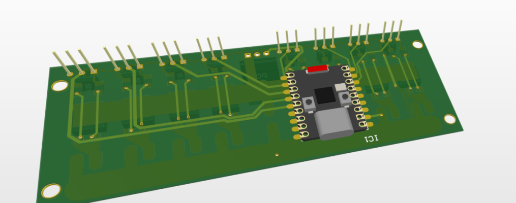
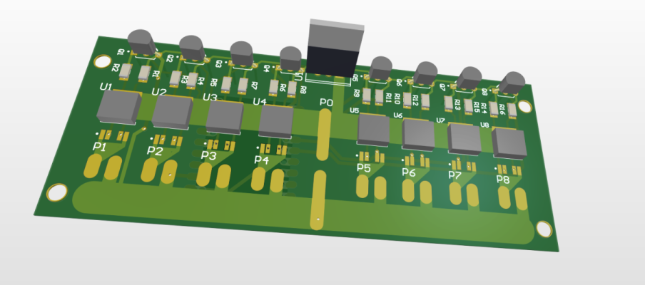
Case prototypes. And yes, I did 3d-print the entire board as a mockup.

IMG_5909.jpeg

IMG_5910.jpeg

IMG_5911.jpeg


The biggest risk so far is thermals: more current, more heat. I've made one change to the parts load out to reduce power consumed by the logic circuit (instead of the buck converter running to 12V, it now runs down to 6.2V and the liner regulators take over from there). It's a single resistor swap, and later builds won't require me to swap it. Each port will consume a little power when switching at max currents, especially near the limit. I'm planning on a few stress tests to determine where that limit lies (7 DC loads, one for each port). Of course, I could have flubbed up something major and then we wait 2-3 weeks for RevB to show up with a fix.

I'm working on the Hub and Battery modules next (and a few bonus modules like a fan controller, CO2, vitals, and heater later), and will start writing documentation soon. The GitHub repository is updated including the BOM, Schematic, pick and place, and Gerber files, keeping in spirit of this being Open Source Hardware.

Firmware is still going to be based on ESPHome, which gives great tie in to Home Assistant and with the configuration file being declarative lets you have some pretty advanced customization without having to reinvent the wheel (and a lot of community support), or even understand C/C++. The USB port here goes straight to the ESP32-C3 and you can reflash it to your heart's content.

Of course, if you don't want that, and don't have Home Assistant, you can access the built in web-server for status and control. Or don't even join it to WiFi and just look at the screen :).
 

Minifoot77

Jack of all trades and a master of none
View Badges
Joined
Jul 3, 2022
Messages
695
Reaction score
847
Location
Ottawa
Rating - 0%
0   0   0
So what scale is the banana?
 

yury88

Active Member
View Badges
Joined
Oct 21, 2023
Messages
179
Reaction score
127
Location
indo-pacific
Rating - 0%
0   0   0
What service you are using for pcb+ assembly?
And how much did they charge you for one board?
 

yury88

Active Member
View Badges
Joined
Oct 21, 2023
Messages
179
Reaction score
127
Location
indo-pacific
Rating - 0%
0   0   0
Tried to feed the project to PCBWay, but made some mistakes:
- I didn't realize that pcb is 4-layers. Pcb only will cost 75$+. Is it really needed to use 4-layers pcb for such project?
- BOM for assembly is not following format that they accept, need to make some homework before ordering.

But in the end if will cost me around 150$ for one pcb that is over my budget . I thing I will go with less fancy solution)

By the way, this chips that used is containing 0.1Ohm internal shunt to measure current.
For 7*3A loads is 6.3W heat just from shunts in standby mode. esp32 chips, power jacks also will add some.
So overheating can be a problem.

For example INO260 using build in 0.002 ohms shunt that will result only 0.126W power loose.

Another thing that I can't just accept- for so expensive solution esp32-c3 was chosen. I's lowest grade 1-core solution. Saving 1-2$ on core processor you are limiting firmware that can be used for this.
 
OP
OP
theatrus

theatrus

Valuable Member
View Badges
Joined
Mar 26, 2016
Messages
2,040
Reaction score
3,437
Location
Sacramento, CA area
Rating - 0%
0   0   0
Tried to feed the project to PCBWay, but made some mistakes:
- I didn't realize that pcb is 4-layers. Pcb only will cost 75$+. Is it really needed to use 4-layers pcb for such project?
- BOM for assembly is not following format that they accept, need to make some homework before ordering.

But in the end if will cost me around 150$ for one pcb that is over my budget . I thing I will go with less fancy solution)

By the way, this chips that used is containing 0.1Ohm internal shunt to measure current.
For 7*3A loads is 6.3W heat just from shunts in standby mode. esp32 chips, power jacks also will add some.
So overheating can be a problem.

For example INO260 using build in 0.002 ohms shunt that will result only 0.126W power loose.

Another thing that I can't just accept- for so expensive solution esp32-c3 was chosen. I's lowest grade 1-core solution. Saving 1-2$ on core processor you are limiting firmware that can be used for this.

INA260 isn’t a high side power switch with over current protection built in, only the shunt and amplifier. I only looked at high side power switches with OCP for this application. Yes they all carry a much higher RdsOn, and at max current get spicy. I may regret this later and have to derate total current.

Board is four layer because outside the initial setup cost it’s a wash in per unit pricing and gives a lot nicer of a layout and ground setup. Note the outer layers should be done at 2oz copper to meet current specs.

C3 is plenty and the hard wired USB-Serial port saves even more (unique) parts.

As for the cost it’s a bit low, as this is a 2oz board for the outer layers + ENIG. However the costs drop off for the special setup fees even at the 20 unit mark. Same goes for assembly where feeder loading (= unique parts in the PnP) is the dominant cost at low volume.
 

yury88

Active Member
View Badges
Joined
Oct 21, 2023
Messages
179
Reaction score
127
Location
indo-pacific
Rating - 0%
0   0   0
Things that I'm going to control cost less than this build, so I made my own version of the "Poor Man" DC Buddy.:)
With ESP32-S3 onboard and BTS6143 high side switch, I can buy them for 0.5$/pcs.

40x100mm 5$ board size and with case it will be smaller than banana)
Total build ~15$
Screenshot 2024-05-14 152420.png Screenshot 2024-05-14 152300.png
 
OP
OP
theatrus

theatrus

Valuable Member
View Badges
Joined
Mar 26, 2016
Messages
2,040
Reaction score
3,437
Location
Sacramento, CA area
Rating - 0%
0   0   0
Things that I'm going to control cost less than this build, so I made my own version of the "Poor Man" DC Buddy.:)
With ESP32-S3 onboard and BTS6143 high side switch, I can buy them for 0.5$/pcs.

40x100mm 5$ board size and with case it will be smaller than banana)
Total build ~15$
Screenshot 2024-05-14 152420.png Screenshot 2024-05-14 152300.png

Looks like a good fit. The DPAKs aren’t too large (unlike the larger D2PAK). Not pairing it with an INA2xx current amp on each channel? The current output at low values is all over the place from the data sheet and requires per device calibration (this is common on the Infineon switches)

Also do current trace width calculations - 1oz is probably not sufficient unless you remove the top mask layer in sections and flood the trace with solder on top (low budget trade thickening).

Also watch for the antenna. Smacking it right on top of a large copper plane isn’t ideal. Those C3 mini boards seem to source the cheapest chip antenna known and some work terribly.

Also, feel free to start your own thread for this build. Happy to trade ideas of course but I want to see this “in reality” (as far as internet pictures go), but also leave space for my updates :)
 
Last edited:

yury88

Active Member
View Badges
Joined
Oct 21, 2023
Messages
179
Reaction score
127
Location
indo-pacific
Rating - 0%
0   0   0
Looks like a good fit. The DPAKs aren’t too large (unlike the larger D2PAK). Not pairing it with an INA2xx current amp on each channel? The current output at low values is all over the place from the data sheet and requires per device calibration (this is common on the Infineon switches)

Also do current trace width calculations - 1oz is probably not sufficient unless you remove the top mask layer in sections and flood the trace with solder on top (low budget trade thickening).

Also watch for the antenna. Smacking it right on top of a large copper plane isn’t ideal. Those C3 mini boards seem to source the cheapest chip antenna known and some work terribly.

Also, feel free to start your own thread for this build. Happy to trade ideas of course but I want to see this “in reality” (as far as internet pictures go), but also leave space for my updates :)
The Ina260 has decent specs, but its i2c chips. Only 4 addresses are supported, so for 8 channels, you need to use both I2C channels in esp32.

And it needs to write custom, asynchronous components for esp32 home... In C code, not my favorite part:)


I'm too busy with other projects to put too much effort into this.

Seeing Watts in HA is cool, but not the most important thing; just on/off with short circuit protection is good enough.
 

yury88

Active Member
View Badges
Joined
Oct 21, 2023
Messages
179
Reaction score
127
Location
indo-pacific
Rating - 0%
0   0   0
Also do current trace width calculations - 1oz is probably not sufficient unless you remove the top mask layer in sections and flood the trace with solder on top (low budget trade thickening)
Made calculations today, my design is ok for 2*10amps with 1oz copper.
Track length 42mm, width 6.5mm, external layer.
Heat on max load 12C, power loss 0.35W

Good enough for these cheap build, heavy loads can be just connected to central ports to reduce heat.
 

braaap

Valuable Member
View Badges
Joined
Jul 16, 2015
Messages
1,041
Reaction score
931
Location
Montana
Rating - 100%
3   0   0
I love coming and reading these updates. But I'm not smart enough to get most of it.

I'm still trying to reproduce the NB driver boards that you could likely do in 2-3 hours lol
 

esquare

Well-Known Member
View Badges
Joined
Apr 10, 2017
Messages
629
Reaction score
673
Location
Northwest Indiana
Rating - 0%
0   0   0
I love coming and reading these updates. But I'm not smart enough to get most of it.

I'm still trying to reproduce the NB driver boards that you could likely do in 2-3 hours lol
My thoughts exactly. I am enjoying following this thread as I find the concept very interesting but most of it goes over my head.
 

EeyoreIsMySpiritAnimal

Just another girl who likes fish
View Badges
Joined
May 14, 2019
Messages
13,580
Reaction score
20,176
Location
Spring, Texas
Rating - 0%
0   0   0
I love coming and reading these updates. But I'm not smart enough to get most of it.

I'm still trying to reproduce the NB driver boards that you could likely do in 2-3 hours lol

My thoughts exactly. I am enjoying following this thread as I find the concept very interesting but most of it goes over my head.

I'm even more lost, lol.
@theatrus , for us "non-electronical" folks, can you recap how the common hobbyist might use the end product? (And dumb it down more than the first post ;) )
 
OP
OP
theatrus

theatrus

Valuable Member
View Badges
Joined
Mar 26, 2016
Messages
2,040
Reaction score
3,437
Location
Sacramento, CA area
Rating - 0%
0   0   0
I'm even more lost, lol.
@theatrus , for us "non-electronical" folks, can you recap how the common hobbyist might use the end product?

Sure thing!

Step 1: Plug in 200W power supply, plug in to the DCBuddy.
Step 2: Unplug all your VorTech, Gyre, DC skimmer, etc power supplies and put them in storage. The main use case is 24V equipment - most DC pumps and power heads run on 24V.
Step 3: Plug the VorTech, Gyres, etc (any 24V equipment) into the DCBuddy.
Step 4: Enjoy all the space and outlets you got back.

Step 5-N: If you use Home Assistant, get current monitoring and on/off control from the HA UI. Or browse to the local web page and get the same. Or just ignore this function entirely!

Coming soon is redundant power supplies, 12V output, and battery backup.
 

Building with glass and silicone: Have you ever built a tank or had a custom tank built?

  • I have built an aquarium.

    Votes: 27 15.2%
  • I have had a custom tank built.

    Votes: 40 22.5%
  • I have never built a tank or had a custom tank built.

    Votes: 103 57.9%
  • Other.

    Votes: 8 4.5%
Back
Top