AI Hydra Fan Connector Repair - Significant Corrosion

_AV

Well-Known Member
View Badges
Joined
Oct 3, 2019
Messages
679
Reaction score
695
Rating - 0%
0   0   0
My previous electronic equipment repair projects

Radion XR15:
Radion XR30:

Imagine a problem with a connector breaking off the board. Usually not a big deal. Worst case - a couple of torn traces and a new connector. Unless, of course, we are talking about the reef gear. In which case, we have to expect things breaking in new and unusual ways!

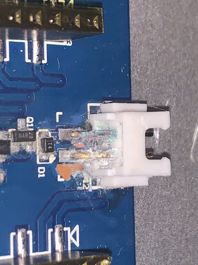
This is certainly the case with this AI Hydra light. It was also a mail in service request from a fellow reefer. So I am not exactly sure how this connector came off the board, but... well, take a look at this:
IMG_0315.JPG

What??? The entire fan circuit is missing. Every. Single. Component.
The area is covered in a thick layer of corrosion to the point you can't tell what is what:
0002.jpg
0003.jpg

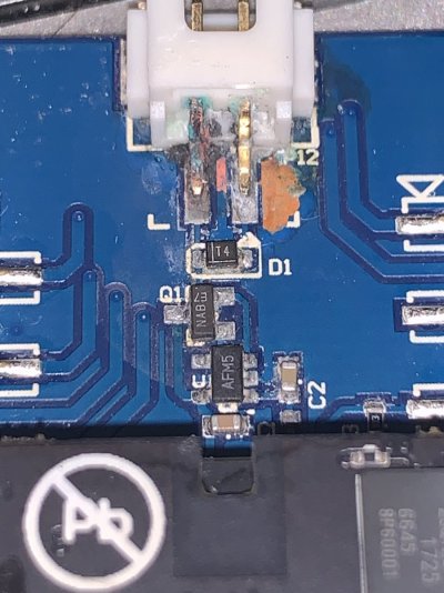
Let's clean up the corrosion and see if there is anything left below it:
0014.jpg
0015.jpg

Now it is clear that at least some traces and pads corroded away entirely. Both pads from the connector are no longer connected to the board circuit. Looks like there should be a diode, a resistor and some other component.

This is what the fan control circuit should look like:
0013.jpg

The third missing component turns out to be a small mosfet. This makes sense, something needs to help the controller switch the fan on and off after all.

Let's get started on restoring the board traces. This time, instead of using the jumpers, I decided to use copper to lay out the new traces.
0019.jpg 0018.jpg

As you can see, it's not all that bad. Just a couple of runs from the connector pads to link them to the diode and the mosfet, while carefully avoiding unrelated traces in close proximity.
Anyway, we are ready to layout the missing components:
0026.jpg

At this point, the fan should work once plugged in. But all of this exposed copper will corrode very quickly again. And then the corrosion will push the new components off the board again.
To solve this, I'll put a good layer of conformal coating over the entire area:
0028.jpg

This coating needs to be cured to harden it:
0031.jpg

Once hardened, the conformal coating not only protects against corrosion, but also helps to hold my traces to the board.
0030.jpg

Now it's time to test if the new fan circuit actually works:
IMG_0344.JPG

My leading theory on why the damage to the board was so significant is a sequence of events with the old fan failing and shorting first. The short caused a part of the circuit to burn out. You can actually see a small hole in the board right next to the diode where a part of the trace used to be. The short on the board made the black coating to flake off exposing copper on several traces. Copper usually corrodes violently, which might have been enough to push all the circuit components off the board.
Either way, the light is now working and the board circuit is corrosion resistant.
 

Ron Reefman

Lets Go Snorkeling!
View Badges
Joined
Aug 12, 2012
Messages
9,285
Reaction score
20,887
Location
SW Florida
Rating - 0%
0   0   0
nice work
 

Sherief Singer

New Member
View Badges
Joined
Dec 7, 2017
Messages
5
Reaction score
1
Rating - 0%
0   0   0
@_AV, I have the same problem with all 3 of my 26HD lights over a 6 month period.... all seems to be in the fan circuit area. if you don't mind me asking, where did you order the components from? also, do you have any idea what the capacitor and resistor values or SMD codes are? Are the caps just for filtering/necessary?

Thanks again!
 
OP
OP
_AV

_AV

Well-Known Member
View Badges
Joined
Oct 3, 2019
Messages
679
Reaction score
695
Rating - 0%
0   0   0
I order most of my components from digikey/mouser/newark to ensure they are original and of high quality. It's getting much harder now with major shortages everywhere.

I don't know hydra 26 specific circuitry details without looking closely at it. There is no capacitor in the fan circuit. The resistor is marked 1003, which suggests that it's 100 kOhm.
 
OP
OP
_AV

_AV

Well-Known Member
View Badges
Joined
Oct 3, 2019
Messages
679
Reaction score
695
Rating - 0%
0   0   0
Finally got around to record a fan circuit repair video for a 26 HD. Hope this will be helpful. Please like and subscribe to keep me motivated :)


hhaase

Active Member
View Badges
Joined
Nov 11, 2019
Messages
415
Reaction score
355
Rating - 0%
0   0   0
If I had to venture a guess, something (probably Q1) had been reworked at the factory with aqueous flux and they didn't properly clean it. You can see the corrosion migrating along the traces. The corrosion is consistent with an aggressive flux as well. Once the corrosion starts, it's hard to stop.
 
OP
OP
_AV

_AV

Well-Known Member
View Badges
Joined
Oct 3, 2019
Messages
679
Reaction score
695
Rating - 0%
0   0   0
There's no doubt there are assembly issues across all brands.
Then there is water damage and... also, let's call it, pet damage as well. Both contribute significantly to the number of corroded units I receive for repair.

Here's an example of one of the worst corrosion on a Radion light I've seen:
image1.jpg
image2.jpg


This corrosion was a surprise the the owner.
It was a no repair:
 

Biologic

Active Member
View Badges
Joined
Aug 25, 2014
Messages
369
Reaction score
268
Location
USA
Rating - 0%
0   0   0
Finally got around to record a fan circuit repair video for a 26 HD. Hope this will be helpful. Please like and subscribe to keep me motivated :)


I just tried to attempt to clean with 95% alcohol the fan circuitry of a used AI Hydra 26. Mine was in much better condition. I used a very fine extra soft tooth brush sweeping the pads and semi-conductors. I did not get a response from the fan. I tested the fan with a 12 volt power supply. Spun up with no issues. I still have some corrosion. Do you think I could reflow what solder I have here by touching a soldering iron to the pads to reset the various places with corrosion?

The first pic is the before, the second pic with the white molex connector on the board facing the 12 o'clock position is the after.
 

Attachments

  • IMG_0020.JPG
    IMG_0020.JPG
    186.7 KB · Views: 52
  • IMG_0028.JPG
    IMG_0028.JPG
    182.6 KB · Views: 61
OP
OP
_AV

_AV

Well-Known Member
View Badges
Joined
Oct 3, 2019
Messages
679
Reaction score
695
Rating - 0%
0   0   0
I just tried to attempt to clean with 95% alcohol the fan circuitry of a used AI Hydra 26. Mine was in much better condition. I used a very fine extra soft tooth brush sweeping the pads and semi-conductors. I did not get a response from the fan. I tested the fan with a 12 volt power supply. Spun up with no issues. I still have some corrosion. Do you think I could reflow what solder I have here by touching a soldering iron to the pads to reset the various places with corrosion?

The first pic is the before, the second pic with the white molex connector on the board facing the 12 o'clock position is the after.
The original picture looks pretty bad. While you certainly can reflow the joints and it should help keep the corrosion away, since you mentioned that the fan is still not working, I'm willing to bet that the original corrosion on the connector damaged the actual fan circuitry (any combination of U1, Q1 and D1). You can test it with a voltmeter to be sure, but in my experience when the connector is this badly corroded, it likely causes a dead short and the circuit is not really designed to handle that.
 

Biologic

Active Member
View Badges
Joined
Aug 25, 2014
Messages
369
Reaction score
268
Location
USA
Rating - 0%
0   0   0
The original picture looks pretty bad. While you certainly can reflow the joints and it should help keep the corrosion away, since you mentioned that the fan is still not working, I'm willing to bet that the original corrosion on the connector damaged the actual fan circuitry (any combination of U1, Q1 and D1). You can test it with a voltmeter to be sure, but in my experience when the connector is this badly corroded, it likely causes a dead short and the circuit is not really designed to handle that.

I do have a multi meter, though I am not great at using it. I have a very basic understanding. With the unit off and unplugged, I set it to 1 ohm, I tested the resistance across the terminals of the connectors. I was able to register that current was moving through the terminals. When I touched it to another trace around the fan circuitry, I found current was moving through.

I would have to individually test U1, Q1 and D1 as well?

Also looking at the terminals where the fan connector is, it still looks like I have some cleaning to do. I used a wooden tooth pick as to limit my possible damage I could do to the board. The point is not as sharp and its softer than the metal dental picks that I could use.
 
OP
OP
_AV

_AV

Well-Known Member
View Badges
Joined
Oct 3, 2019
Messages
679
Reaction score
695
Rating - 0%
0   0   0
I do have a multi meter, though I am not great at using it. I have a very basic understanding. With the unit off and unplugged, I set it to 1 ohm, I tested the resistance across the terminals of the connectors. I was able to register that current was moving through the terminals. When I touched it to another trace around the fan circuitry, I found current was moving through.

I would have to individually test U1, Q1 and D1 as well?

Also looking at the terminals where the fan connector is, it still looks like I have some cleaning to do. I used a wooden tooth pick as to limit my possible damage I could do to the board. The point is not as sharp and its softer than the metal dental picks that I could use.
Yeah, if I were repairing this, I'd be removing the molex and likely replacing it after cleaning and tinting the pads. On the last picture, the left pin is severely discolored, which suggests a thick oxidation layer, which likely does not conduct reliably anymore.
With a multimeter, and the molex removed, I'd be testing voltages instead of resistance at the fan pins, inputs and outputs of Q1 and U1. I believe the hydra fan is 5v (don't test it with a 12v power supply). So I would be looking for 5v on light start up and then again when it warms up sufficiently at high intensity.
 

Biologic

Active Member
View Badges
Joined
Aug 25, 2014
Messages
369
Reaction score
268
Location
USA
Rating - 0%
0   0   0
Yeah, if I were repairing this, I'd be removing the molex and likely replacing it after cleaning and tinting the pads. On the last picture, the left pin is severely discolored, which suggests a thick oxidation layer, which likely does not conduct reliably anymore.
With a multimeter, and the molex removed, I'd be testing voltages instead of resistance at the fan pins, inputs and outputs of Q1 and U1. I believe the hydra fan is 5v (don't test it with a 12v power supply). So I would be looking for 5v on light start up and then again when it warms up sufficiently at high intensity.

so what I should do is test with the board on So I can see if there’s power being delivered to the pins themselves?g
 

Biologic

Active Member
View Badges
Joined
Aug 25, 2014
Messages
369
Reaction score
268
Location
USA
Rating - 0%
0   0   0

oh I should add, it runs lights up perfectly fine, just no fan. I could add a 24 volt muffin fan off my apex if I cannot get this resolved.

should I stop while I am ahead? I could potentially cause more harm than good.

thank you for your inspiring YouTube channel. I was an early subscriber.
 
OP
OP
_AV

_AV

Well-Known Member
View Badges
Joined
Oct 3, 2019
Messages
679
Reaction score
695
Rating - 0%
0   0   0
oh I should add, it runs lights up perfectly fine, just no fan. I could add a 24 volt muffin fan off my apex if I cannot get this resolved.

should I stop while I am ahead? I could potentially cause more harm than good.

thank you for your inspiring YouTube channel. I was an early subscriber.
Thank you for being a subscriber. Much appreciated.

I think it all depends on your comfort level and the skills. I don't think there is a whole lot of risk in measuring a life fan circuit. But I do understand that it still requires precision probes and a steady hand.

Adding a separate fan is certainly an option.
You can always mail it to me for a repair as well ;)
 

Biologic

Active Member
View Badges
Joined
Aug 25, 2014
Messages
369
Reaction score
268
Location
USA
Rating - 0%
0   0   0
Thank you for being a subscriber. Much appreciated.

I think it all depends on your comfort level and the skills. I don't think there is a whole lot of risk in measuring a life fan circuit. But I do understand that it still requires precision probes and a steady hand.

Adding a separate fan is certainly an option.
You can always mail it to me for a repair as well ;)

I am going to give it the old college try. If that doesn't work, it's coming to you. I really need a microscope. haha!
 

Reefing threads: Do you wear gear from reef brands?

  • I wear reef gear everywhere.

    Votes: 15 21.4%
  • I wear reef gear primarily at fish events and my LFS.

    Votes: 2 2.9%
  • I wear reef gear primarily for water changes and tank maintenance.

    Votes: 0 0.0%
  • I wear reef gear primarily to relax where I live.

    Votes: 10 14.3%
  • I don’t wear gear from reef brands.

    Votes: 37 52.9%
  • Other.

    Votes: 6 8.6%
Back
Top