
OP
OP
indeed a small
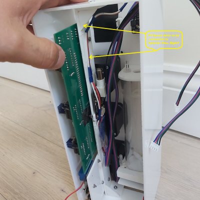
the fan is still preferred as its easier to mount and saves a lot of space. there would be not enough space in my enclosure for other motor unfortunately
indeed a small motor would be better - does not need a lot of torque, its just that fans have almost no torque at all..Or just use a normal DC motor with higher torque and put an acryl disc with magnets on its axis. Fans really aren't meant to push any load more than air.
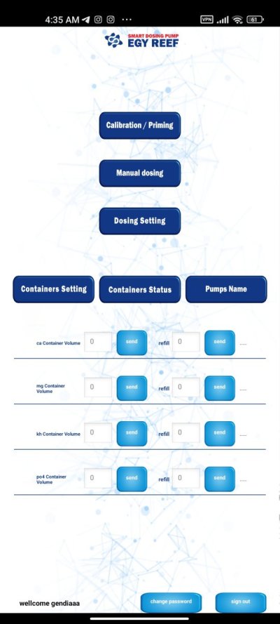
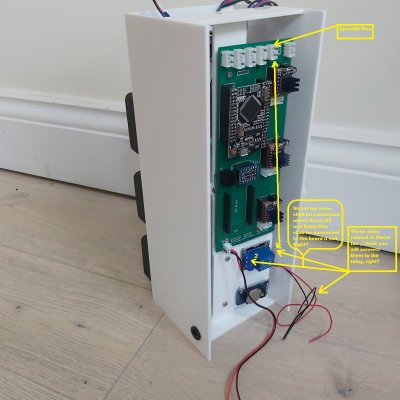
That's a battery powered magnetic stirrer i made that i use for mixing alkalinity and calcium solutions.
.jpg")
the fan is still preferred as its easier to mount and saves a lot of space. there would be not enough space in my enclosure for other motor unfortunately


")