
The wife (TD2K) and I had a 225 gallon custom tank built. It sets inside our house with three plastic fish in it waiting to be completed. She built an amazing monster sump for it and we are purchasing a piece at a time. She is an Engineer so as with any project there is a lot of preplanning. We wanted to have an LED light system for our new tank so we decided to build an LED test system for our current 55 gallon reef tank.
We started off doing research. We didn’t want to invest a ton of money and not get the right thing or worse yet kill our coral. So we started going on forums and asking questions, lots of questions. We wanted to know how many LEDs we would need for our standard 55 gallon tank. Or, how many LEDs do we need for a certain depth of water or square foot of water. No one seemed to know. What we did hear was x amount of LEDs “SHOULD†work. LOL… “SHOULD†Well I felt like there should be some sort of science to it. What we did learn is that certain types of coral grow differently in different tanks. We heard a bunch of discussion over what works and what doesn’t which seemed to end up like some school yard verbal argument ending with “My daddy can whip your daddy!â€
I will attempt to share some of the things we learned and the process in which we built our lights. Bear with me as I am not the Engineer! I R COP! I hope this will help answer some of the questions you may have if you are thinking about building a LED system. It is worth every penny. It is better than most systems and much, much, cheaper. Most importantly if I built it, so can you…. Trust me.
The first thing we did was purchase a kit from a great company. We went with a kit that seemed to be overkill. We purchased:
36 Cree Ultra Premium LED Kit which included
3 Mean well Dimmable Drivers ELN-60-48D (more the analog version for dimming)
1 Mean well Dimmable Drivers ELN-60-48D (this was additional)
14 Royal Blue XP-E (with 80* optics)
14 Cool White XP-G (with 80* optics)
4 Neutral White XP-G (won't use optics)
4 Blue XP-E (won't use optics)
2 Anodized Heat Sinks 6â€x 9†with fans and splash shields and hanging kit
1 DIY two color dimming kit
1 Thermal adhesive
We added power strips with built in timers and misc parts like terminal strips and cat6 wire.
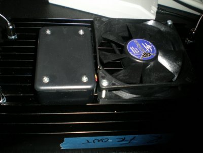
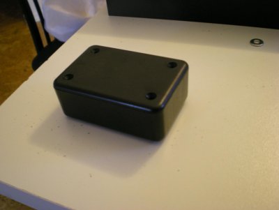
This is the overall idea of what we built. We attached LEDs to 2 heat sinks. The blue and white LEDs have separate circuits on each heat sink so that we can mix the light with our dimmer. The heat sinks were mounted above the tank in such a way we can adjust their position up or down and from left to right. A junction box and fan was mounted on each heat sink. The 2 wires from the blue LED circuit and the 2 wires from the white LED circuit along with the two fan wires would connect to the cat 6 wire in the junction box on the heat sink. The cat 6 cable would then travel down the back of the tank to a piece of ¾ inch poly we used for a mounting board for all of our devices. The cat 6 connected to a terminal strip in which the fan power and drivers were connected. This would allow easy trouble shooting for future problems.
We planned to use two heat sinks for the lights, one on each side of the tank. Originally we ordered the predrilled and tapped heat sinks so that we could attach the LEDs to the heat sink with screws. This was a more expensive option so we went with it. What we learned is that it is easier to use the thermal adhesive to mount the LEDs. It is safer because if you mount them with screws the screw heads are extremely close to the terminal pads that get soldered. The thought being that condensation or salt buildup or any other thing that could go wrong probably would. It is better to use adhesive because you can get the blues and the whites closer for better color mixing. But, most importantly it is cheaper. We have heard of people using L shaped aluminum channel instead of heat sinks for even more of a money savings. Whatever you do make sure the LEDs stay cool to the touch or you will be buying more long before you should.
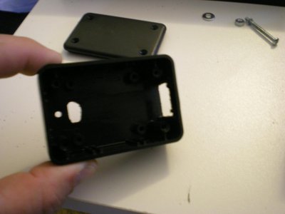
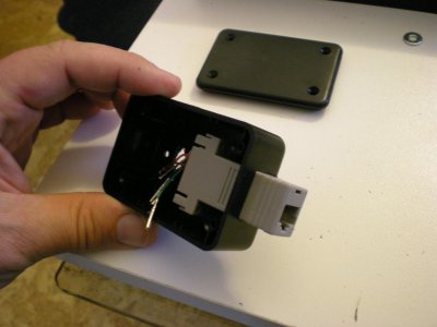
We wanted to make really nice connections to be able to disconnect the lights easily from the cat 6 or from the drivers. I played around with a cat 5 female connector but the wire looked so very small inside the connector we scrapped the idea and just soldered the connections on in the junction box and used terminal blocks on the mounting board side. It works ok but for our bigger tank I will find some nice connectors to use to make it look clean.
Cat 6 cable was used instead of cat 5 because it is 23 gauge instead of the standard 24 gauge for cat5. On our next tank I will probably find a 20 gauge multi conductor with stranded wire. I know we are only pushing 1 amp but the less resistance the better.
We mounted our LEDs using the thermal adhesive. Great care was used when soldering as explained above because of the tiny pads. If any flux goes over the edge you could short out your LEDs. These tabs are right on the very edge so it wouldn’t be hard to screw it up. In the future I will use different colored wire for the white LEDs vs. the blue LEDs. Just makes it easier to trace and identify.
Once the LEDs were mounted we checked our LED drivers to insure we were not pushing to many amps. We popped the cover off of the driver and turned the adjustment all the way down prior to powering the LEDs. Once it was turned down we hooked up our meter and metered the blue driver and LEDs only. We turned the driver up until it read 850mA. We did this because their max rating is 900mA. Anything over that would shorten their lifespan badly. We did the same thing for white but they have a much higher rating. We turned those drivers up to 1250mA. We have a white driver and a blue driver for each side. After that was complete everything else was pretty much self explanatory.
We were using fluorescent lights before so when we finally hooked everything up we turned on the LEDs and BAM! Great looking light. We didn’t realize how bright the LEDs were until later when our mushrooms were saying NO! We went to Custom Reef Creations and rented a PAR meter. We learned some amazing things about our LEDs and turned the LEDs way down right away…lol… “Way Downâ€. FYI when doing this slowly acclimate your tank to your LEDs …. “SLOWLY!â€
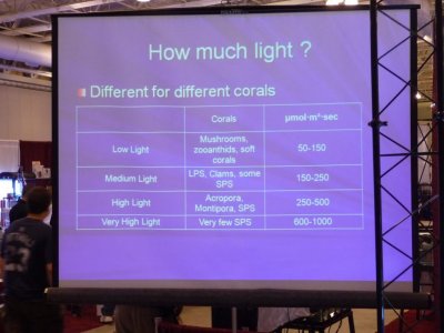
Our Lights are turned down to about 50% and we plan to very slowly increase them over the next 10-14 days. We now know what PAR our tank needs and added a picture that contains some information on what light coral requires.
We started off doing research. We didn’t want to invest a ton of money and not get the right thing or worse yet kill our coral. So we started going on forums and asking questions, lots of questions. We wanted to know how many LEDs we would need for our standard 55 gallon tank. Or, how many LEDs do we need for a certain depth of water or square foot of water. No one seemed to know. What we did hear was x amount of LEDs “SHOULD†work. LOL… “SHOULD†Well I felt like there should be some sort of science to it. What we did learn is that certain types of coral grow differently in different tanks. We heard a bunch of discussion over what works and what doesn’t which seemed to end up like some school yard verbal argument ending with “My daddy can whip your daddy!â€
I will attempt to share some of the things we learned and the process in which we built our lights. Bear with me as I am not the Engineer! I R COP! I hope this will help answer some of the questions you may have if you are thinking about building a LED system. It is worth every penny. It is better than most systems and much, much, cheaper. Most importantly if I built it, so can you…. Trust me.
The first thing we did was purchase a kit from a great company. We went with a kit that seemed to be overkill. We purchased:
36 Cree Ultra Premium LED Kit which included
3 Mean well Dimmable Drivers ELN-60-48D (more the analog version for dimming)
1 Mean well Dimmable Drivers ELN-60-48D (this was additional)
14 Royal Blue XP-E (with 80* optics)
14 Cool White XP-G (with 80* optics)
4 Neutral White XP-G (won't use optics)
4 Blue XP-E (won't use optics)
2 Anodized Heat Sinks 6â€x 9†with fans and splash shields and hanging kit
1 DIY two color dimming kit
1 Thermal adhesive
We added power strips with built in timers and misc parts like terminal strips and cat6 wire.
This is the overall idea of what we built. We attached LEDs to 2 heat sinks. The blue and white LEDs have separate circuits on each heat sink so that we can mix the light with our dimmer. The heat sinks were mounted above the tank in such a way we can adjust their position up or down and from left to right. A junction box and fan was mounted on each heat sink. The 2 wires from the blue LED circuit and the 2 wires from the white LED circuit along with the two fan wires would connect to the cat 6 wire in the junction box on the heat sink. The cat 6 cable would then travel down the back of the tank to a piece of ¾ inch poly we used for a mounting board for all of our devices. The cat 6 connected to a terminal strip in which the fan power and drivers were connected. This would allow easy trouble shooting for future problems.
We planned to use two heat sinks for the lights, one on each side of the tank. Originally we ordered the predrilled and tapped heat sinks so that we could attach the LEDs to the heat sink with screws. This was a more expensive option so we went with it. What we learned is that it is easier to use the thermal adhesive to mount the LEDs. It is safer because if you mount them with screws the screw heads are extremely close to the terminal pads that get soldered. The thought being that condensation or salt buildup or any other thing that could go wrong probably would. It is better to use adhesive because you can get the blues and the whites closer for better color mixing. But, most importantly it is cheaper. We have heard of people using L shaped aluminum channel instead of heat sinks for even more of a money savings. Whatever you do make sure the LEDs stay cool to the touch or you will be buying more long before you should.
We wanted to make really nice connections to be able to disconnect the lights easily from the cat 6 or from the drivers. I played around with a cat 5 female connector but the wire looked so very small inside the connector we scrapped the idea and just soldered the connections on in the junction box and used terminal blocks on the mounting board side. It works ok but for our bigger tank I will find some nice connectors to use to make it look clean.
Cat 6 cable was used instead of cat 5 because it is 23 gauge instead of the standard 24 gauge for cat5. On our next tank I will probably find a 20 gauge multi conductor with stranded wire. I know we are only pushing 1 amp but the less resistance the better.
We mounted our LEDs using the thermal adhesive. Great care was used when soldering as explained above because of the tiny pads. If any flux goes over the edge you could short out your LEDs. These tabs are right on the very edge so it wouldn’t be hard to screw it up. In the future I will use different colored wire for the white LEDs vs. the blue LEDs. Just makes it easier to trace and identify.
Once the LEDs were mounted we checked our LED drivers to insure we were not pushing to many amps. We popped the cover off of the driver and turned the adjustment all the way down prior to powering the LEDs. Once it was turned down we hooked up our meter and metered the blue driver and LEDs only. We turned the driver up until it read 850mA. We did this because their max rating is 900mA. Anything over that would shorten their lifespan badly. We did the same thing for white but they have a much higher rating. We turned those drivers up to 1250mA. We have a white driver and a blue driver for each side. After that was complete everything else was pretty much self explanatory.
We were using fluorescent lights before so when we finally hooked everything up we turned on the LEDs and BAM! Great looking light. We didn’t realize how bright the LEDs were until later when our mushrooms were saying NO! We went to Custom Reef Creations and rented a PAR meter. We learned some amazing things about our LEDs and turned the LEDs way down right away…lol… “Way Downâ€. FYI when doing this slowly acclimate your tank to your LEDs …. “SLOWLY!â€
Our Lights are turned down to about 50% and we plan to very slowly increase them over the next 10-14 days. We now know what PAR our tank needs and added a picture that contains some information on what light coral requires.