
Evening all,
First time poster, short time lurker. English is my first language, but still expect errors...
Ive seen some setups and good walk throughs using relay banks or using L298D circuits to control motors. And honestly i can achieve this as i have the parts.
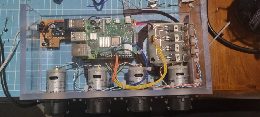
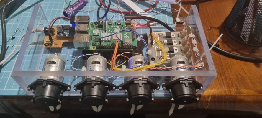
However, my lightbulb moment is this and for simplicity il stick to a 2 motor controller using 2x TIP122 and 1 relay. I would post a circuit, but im on my mobile.
Set up a 5v SPDT relay in equipment tab to switch a relay on or off depending what doser motor you want to drive. Switching is achieved through the timer tab. Using gpio18 (jack0) route it to the Common on the relay, and then NO routed to Motor1 TIP122 base and NC to Motor2 TIP122 base.
This way your PWM signal is only sent to 1 of 2 motors depending on if your relay is energised.
My circuit and question:
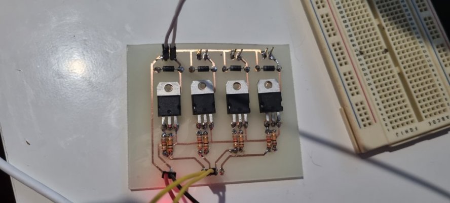
Circuit has a 800(ish)ohm resistor from pwm to base, collector to 1 side of motor, other side to 12v with a 1N4001 diode across the motor terminals to protect against EMF (despite the TIP122 having internal protection) and emitter to gnd with no resistor. I see this circuit having benefit over a l298d due to less inputs from the rpi. And i can achieve this relay circuit using the l298d as well. But are there and benefits to a l298d over a tip122 circuit?
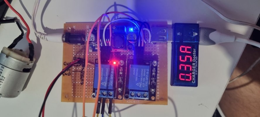
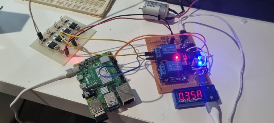
Ive got the l298d circuit set up to control 2 motors substituting 12v input for 5v (waiting on motors in the post) and have it working in reefpi to blink an led but it requires a timer for relay on and off (to provide pwm to either side of the L298d) followered by a timer to turn the motor direction rpi pin on and off and finally a timer to turn the doser on for xx seconds.
Using the TIP122 would mean i can cut out timers for 4motor direction control pins for each L298d, simplifying the reefpi timers and the circuit.
I hope this makes sense. I will attempt to throw up a wiring diagram of each of the 2 options tomorrow and the reefpi configuration for each once i jump on my pc.
First time poster, short time lurker. English is my first language, but still expect errors...
Ive seen some setups and good walk throughs using relay banks or using L298D circuits to control motors. And honestly i can achieve this as i have the parts.
However, my lightbulb moment is this and for simplicity il stick to a 2 motor controller using 2x TIP122 and 1 relay. I would post a circuit, but im on my mobile.
Set up a 5v SPDT relay in equipment tab to switch a relay on or off depending what doser motor you want to drive. Switching is achieved through the timer tab. Using gpio18 (jack0) route it to the Common on the relay, and then NO routed to Motor1 TIP122 base and NC to Motor2 TIP122 base.
This way your PWM signal is only sent to 1 of 2 motors depending on if your relay is energised.
My circuit and question:
Circuit has a 800(ish)ohm resistor from pwm to base, collector to 1 side of motor, other side to 12v with a 1N4001 diode across the motor terminals to protect against EMF (despite the TIP122 having internal protection) and emitter to gnd with no resistor. I see this circuit having benefit over a l298d due to less inputs from the rpi. And i can achieve this relay circuit using the l298d as well. But are there and benefits to a l298d over a tip122 circuit?
Ive got the l298d circuit set up to control 2 motors substituting 12v input for 5v (waiting on motors in the post) and have it working in reefpi to blink an led but it requires a timer for relay on and off (to provide pwm to either side of the L298d) followered by a timer to turn the motor direction rpi pin on and off and finally a timer to turn the doser on for xx seconds.
Using the TIP122 would mean i can cut out timers for 4motor direction control pins for each L298d, simplifying the reefpi timers and the circuit.
I hope this makes sense. I will attempt to throw up a wiring diagram of each of the 2 options tomorrow and the reefpi configuration for each once i jump on my pc.


")