
Navigation
Install the app
How to install the app on iOS
Follow along with the video below to see how to install our site as a web app on your home screen.
Note: This feature may not be available in some browsers.
More options
You are using an out of date browser. It may not display this or other websites correctly.
You should upgrade or use an alternative browser.
You should upgrade or use an alternative browser.
DIY Alkalinity Monitor
- Thread starter Borat
- Start date
- Tagged users None


OP
OP
The volatge on pins should not be affected by the chip.. check quality of soldering..learned another trick with the multimeter
Yes both beep at the correct pin
Maybe the issue is the Arduino?
Only getting 2v on Arduino between gnd and 5V pin
No volts on Arduino between gnd and VIN
Thanks again for your time!The volatge on pins should not be affected by the chip.. check quality of soldering..
I’ll take a look at the soldering again. Hopefully it isn’t a damaged board. I hate trying to remove broken components.

OP
OP
The 5v is input, if you measure 5v pin and GND, it should not matter whether the chip is damaged or not..Thanks again for your time!
I’ll take a look at the soldering again. Hopefully it isn’t a damaged board. I hate trying to remove broken components.
I would also check voltage of the voltage regulator pins, left (VIN) and mid (GND) legs should read 12v and right (VOUT) and mid-leg (GND) should read 5v..
Did some work on sodering and the arduino works great now.The 5v is input, if you measure 5v pin and GND, it should not matter whether the chip is damaged or not..
I would also check voltage of the voltage regulator pins, left (VIN) and mid (GND) legs should read 12v and right (VOUT) and mid-leg (GND) should read 5v..
5V and lights up without the fan being plugged in.
The voltage regulator pins are 12 V and 5 V.
The ESP board doesn't work. But I think I am going to move forward as the wireless connection is a bonus and I can work that into it later once I have nailed the basics down of this very complicated build.
Hats off to all of you who were able to do this.
OP
OP
There is no reason esp32 would not work.. there may be a chance you got the eap32 chip damaged, but if thats the case it would be obvious as program upload would fail.Did some work on sodering and the arduino works great now.
5V and lights up without the fan being plugged in.
The voltage regulator pins are 12 V and 5 V.
The ESP board doesn't work. But I think I am going to move forward as the wireless connection is a bonus and I can work that into it later once I have nailed the basics down of this very complicated build.
Hats off to all of you who were able to do this.
To upload a new program to eap32 you need to either remove the chip or disconnect the LLC chip: esp32 cannot be programmed if another chip is connected to its rx/tx pins.

ThanksThere is no reason esp32 would not work.. there may be a chance you got the eap32 chip damaged, but if thats the case it would be obvious as program upload would fail.
To upload a new program to eap32 you need to either remove the chip or disconnect the LLC chip: esp32 cannot be programmed if another chip is connected to its rx/tx pins.
I went to bed last night and told my wife I was done with this project.....
back at it today...
I just feel so close
I removed the ESP and the circuit board lost some of its pin hole rings in the proecess. Sooo I think I will have to build a new board to move forward.
Played around with very simple code building today. I was able to learn the difference in OLED and LCD. I have 2 LCD boards with I2C expander chips. Figured out how to write code for this and got the ph probe working. I then transfered it over to you KH code.
It's working some. The LCD display rotates through settings. Will have to do some more tinkering. Or perhaps move back to the OLED version.
Slow progress. This is all new for me.
Do i have to use ESP with the PCB you designed? I think I would be happy just to have a device that I can push a button and it runs my test.
Glad you managed to move foreword and fix some issues . You will make it work am sure
I recommend having and OLED display its way easier to work with . As for the fan in the board the last connection ithe one that labelled FAN in the PCB is for ventilation not stirrer . The stirrer one will be connected to connection called spare D8 i think using relay module
Last question . Am wondering did that PH module you are using works . Can you post a clear pic of it please

yes it was fairly basicGlad you managed to move foreword and fix some issues . You will make it work am sure
I recommend having and OLED display its way easier to work with . As for the fan in the board the last connection ithe one that labelled FAN in the PCB is for ventilation not stirrer . The stirrer one will be connected to connection called spare D8 i think using relay module
Last question . Am wondering did that PH module you are using works . Can you post a clear pic of it please
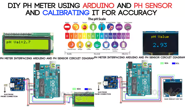
DIY pH Meter using Arduino and pH sensor and Calibrating it for Accuracy - Circuit Schools
Overview In this Quick tutorial, we are interfacing pH sensor and Arduino to make pH meter which can
 www.circuitschools.com
just followed this tutorial with a arduino mega board
OP
OP
No, you don't need ESP32 to run the device and no code modifications are needed either, so that's quite good news. Glad you are progressing - the only way to learn Arduino and electronics generally is by trying, so your struggles are nothing new to meThanks
I went to bed last night and told my wife I was done with this project.....
back at it today...
I just feel so close
I removed the ESP and the circuit board lost some of its pin hole rings in the proecess. Sooo I think I will have to build a new board to move forward.
Played around with very simple code building today. I was able to learn the difference in OLED and LCD. I have 2 LCD boards with I2C expander chips. Figured out how to write code for this and got the ph probe working. I then transfered it over to you KH code.
It's working some. The LCD display rotates through settings. Will have to do some more tinkering. Or perhaps move back to the OLED version.
Slow progress. This is all new for me.
Do i have to use ESP with the PCB you designed? I think I would be happy just to have a device that I can push a button and it runs my test.
")
I also used the same ph board.Glad you managed to move foreword and fix some issues . You will make it work am sure
I recommend having and OLED display its way easier to work with . As for the fan in the board the last connection ithe one that labelled FAN in the PCB is for ventilation not stirrer . The stirrer one will be connected to connection called spare D8 i think using relay module
Last question . Am wondering did that PH module you are using works . Can you post a clear pic of it please
If you change the code as in the sentence below and perform ph calibration, you can use it without problems.
float voltage_4PH = 3.58;
float voltage_7PH = 3.00;
float voltageToPH(float voltage)
{
float ph = (voltage-voltage_7PH)/(voltage_7PH-voltage_4PH)*-4.0 + (voltage-voltage_4PH)/(voltage_4PH-voltage_7PH)*-7.0;
return ph;
}

OP
OP
When you say "did that PH module" work - what's wrong with your PH module? Also which PH module are you using, is that DF Robot v1?Glad you managed to move foreword and fix some issues . You will make it work am sure
I recommend having and OLED display its way easier to work with . As for the fan in the board the last connection ithe one that labelled FAN in the PCB is for ventilation not stirrer . The stirrer one will be connected to connection called spare D8 i think using relay module
Last question . Am wondering did that PH module you are using works . Can you post a clear pic of it please
Nothing wrong with DF Robot V.1.1 which am using . In fact its very good one . but i was asking out of curiosityWhen you say "did that PH module" work - what's wrong with your PH module? Also which PH module are you using, is that DF Robot v1?
OP
OP
But whilst you all admire the superiority of Kazakh technologies, I would like to remind you of the original purpose of this PCB deisgn: a doser with 3 heads..

 www.reef2reef.com
As I have a few printed PCBs, I have recently added a second doser:


The second doser is missing its third dosing head - I have recieved it today and will mount it tomorrow. It took me about 2 hours to put together the second doser..
DIY Trace Elements Doser
In this thread I am going to teach your superior Kazakh engineering skills, specifically how you can build your own doser..
As I have a few printed PCBs, I have recently added a second doser:
The second doser is missing its third dosing head - I have recieved it today and will mount it tomorrow. It took me about 2 hours to put together the second doser..

You are a legend. I salute you!But whilst you all admire the superiority of Kazakh technologies, I would like to remind you of the original purpose of this PCB deisgn: a doser with 3 heads..
DIY Trace Elements Doser
In this thread I am going to teach your superior Kazakh engineering skills, specifically how you can build your own doser..
As I have a few printed PCBs, I have recently added a second doser:
The second doser is missing its third dosing head - I have recieved it today and will mount it tomorrow. It took me about 2 hours to put together the second doser..
great job as always . well doneBut whilst you all admire the superiority of Kazakh technologies, I would like to remind you of the original purpose of this PCB deisgn: a doser with 3 heads..
DIY Trace Elements Doser
In this thread I am going to teach your superior Kazakh engineering skills, specifically how you can build your own doser..
As I have a few printed PCBs, I have recently added a second doser:
The second doser is missing its third dosing head - I have recieved it today and will mount it tomorrow. It took me about 2 hours to put together the second doser..
Its amazing how easy you get all needed parts specially adafruit ones
, i have been waiting for more than 20 days now to get RE board as sparegreat job as always . well doneBut whilst you all admire the superiority of Kazakh technologies, I would like to remind you of the original purpose of this PCB deisgn: a doser with 3 heads..
DIY Trace Elements Doser
In this thread I am going to teach your superior Kazakh engineering skills, specifically how you can build your own doser..
As I have a few printed PCBs, I have recently added a second doser:
The second doser is missing its third dosing head - I have recieved it today and will mount it tomorrow. It took me about 2 hours to put together the second doser..
Its amazing how easy you get all needed parts specially adafruit ones
, i have been waiting for more than 20 days now to get RE board as spare
Similar threads
- Replies
- 0
- Views
- 122
- Replies
- 63
- Views
- 1,815
- Replies
- 11
- Views
- 178
-
- Poll
- Replies
- 88
- Views
- 1,891
New Posts
-

-
-
 AIO Build steveschuergers 90 gallon Goni heavy mixed reef.
- Latest: steveschuerger


