DIY arduino aquarium controller

bct15

2500 Club Member
View Badges
Joined
Nov 20, 2010
Messages
2,845
Reaction score
171
Location
Mississippi
Rating - 0%
0   0   0
So I've been working on a DIY controller the last few days and figured I'd show some of the results. Below is a shot of the LCD feedback with some functionality displayed. (Sorry, all pics taken with my iPhone)

Photo Jun 10, 11 18 43 AM.jpg


I started buying everything to make this when my Apex started messing up and I realized how much it costs to replace everything. This controller will be wireless capable, with an LCD readout, full independent outlet control switched by whatever variables I choose, temp and ph monitoring, separate LED channel dimming and a bunch more.

Incorporated into this controller at this point
16x4 LCD display
8 Mechanical Relay board
Arduino UNO
9 volt power source for dimming of LED driver Meanwell ELN-60-48P

Sitting in bin to be worked in
Water proof temp sensor
Real time clock
Wireless adapter
Ethernet Adapter
Float sensor

Below is a shot of some stuff wired up

Photo Jun 10, 11 07 39 AM.jpg


I have a single relay wired in right now, which is set to on position as natural state. You can see the red light lit up by the relay closest to the breadboard, indicating it is switched close. The relay is currently switched by the button attached to the small red breadboard. The button is representative of any control variable I desire to switch the relay. Below is some shots of it in action.

Button depressed the outlet is ON, indicated by LCD feedback along with the redlight lit up in front of the respective relay. See image below

Photo Jun 10, 11 09 25 AM.jpg


When I press the button, the relay is digitally switched off. Notice the outlet description on the LCD, along with red light no longer lit in front of the relay. The pressing of the button is representative of whatever control variable I choose, such as time, temp, water level, etc. See image below...

Photo Jun 10, 11 09 20 AM.jpg
 
OP
OP
bct15

bct15

2500 Club Member
View Badges
Joined
Nov 20, 2010
Messages
2,845
Reaction score
171
Location
Mississippi
Rating - 0%
0   0   0
The LED brightness is controlled by a potentiometer, which isn't shown in the photos above but below is a pic of it.

Photo Jun 10, 1 33 54 AM.jpg


Simply turn the knob to the right to brighten LEDs, turn knob to the left to dim them. Below is a screenshot of the LED feedback for the brightness, which is the bottom line of the LCD readout. The lower the number the more dim the LED chain is.

Photo Jun 10, 11 10 05 AM.jpg


And here it is with brightness turned up

Photo Jun 10, 11 09 39 AM.jpg


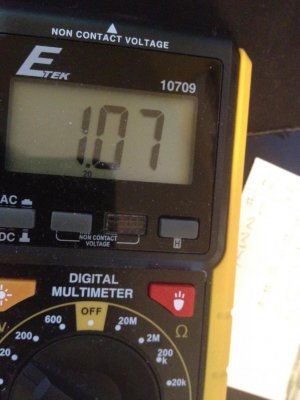
The 5 volt pwm output of the arduino is connected to a separate power source that provides the required ten volts for the Meanwell ELN-60-48P driver by a transistor. The arduino basically converts the power source to a pwm signal. It is hard to get a pic of but below is my best attempt to capture the PWM using a mulimeter.

9 volt ON
Photo Jun 10, 11 11 11 AM.jpg


And the lower part of the step, could capture it very well but it drops lower than 1 volt
 

Attachments

  • Photo Jun 10, 11 10 50 AM.jpg
    Photo Jun 10, 11 10 50 AM.jpg
    94.9 KB · Views: 546

zemuss

Valuable Member
View Badges
Joined
Jun 1, 2010
Messages
1,254
Reaction score
137
Location
Florida
Rating - 0%
0   0   0
So what else are you using with the pot to dim the leds?
 
OP
OP
bct15

bct15

2500 Club Member
View Badges
Joined
Nov 20, 2010
Messages
2,845
Reaction score
171
Location
Mississippi
Rating - 0%
0   0   0
So what else are you using with the pot to dim the leds?

I intend to have the pot control multiple things, so I have the arduino monitoring the position of the pot...then making whatever adjustments digitally. In the case of the led chain it makes adjustments to the pwm signal on the led driver channel going to the meanwell diver.


Sent Via the R2R Forum APP
 

zemuss

Valuable Member
View Badges
Joined
Jun 1, 2010
Messages
1,254
Reaction score
137
Location
Florida
Rating - 0%
0   0   0
Can you share the code?

So you are saying the POT is hooked up to the driver and the arduino?
 

tinctorus

Active Member
View Badges
Joined
Aug 9, 2011
Messages
474
Reaction score
8
Location
South Florida
Rating - 0%
0   0   0
I am just getting started buying the parts to do exactly this, I was originally going to go with a reef angel but decided I would be able to do this for possibly cheaper but more likely the same or more money that but I would have more fun this way as well as having basically ENDLESS options and be able to build this exactly to my needs and specifications
I am going to have my arduino monitor ph, temp, dissolved oxygen, ORP as well as numerous other things I will have it monitor and control
I was planning on purchasing these probes to monitor ph, temp, dissolved oxygen and ORP, can you or anyone give me your thoughts on these probes? They're made by Atlantic scientific and they seem to be really nice probes made to exacting specs, they also make a flow rate meter which would be great for hooking up to the output of your pump to let you know if it's time to clean or rebuild your return pump
https://www.atlas-scientific.com/sensors.html

I was going to order this "probe combo kit" specifically

https://www.atlas-scientific.com/product_pages/kits/sds-kit.html
 
OP
OP
bct15

bct15

2500 Club Member
View Badges
Joined
Nov 20, 2010
Messages
2,845
Reaction score
171
Location
Mississippi
Rating - 0%
0   0   0
I am just getting started buying the parts to do exactly this, I was originally going to go with a reef angel but decided I would be able to do this for possibly cheaper but more likely the same or more money that but I would have more fun this way as well as having basically ENDLESS options and be able to build this exactly to my needs and specifications
I am going to have my arduino monitor ph, temp, dissolved oxygen, ORP as well as numerous other things I will have it monitor and control
I was planning on purchasing these probes to monitor ph, temp, dissolved oxygen and ORP, can you or anyone give me your thoughts on these probes? They're made by Atlantic scientific and they seem to be really nice probes made to exacting specs, they also make a flow rate meter which would be great for hooking up to the output of your pump to let you know if it's time to clean or rebuild your return pump
https://www.atlas-scientific.com/sensors.html

I was going to order this "probe combo kit" specifically

https://www.atlas-scientific.com/product_pages/kits/sds-kit.html

Those probes seem very nice, but that is a lot of money...there is cheaper ways to get some of that. I suggest you get an arduino and play around with it before you buy all of those probes.
 
OP
OP
bct15

bct15

2500 Club Member
View Badges
Joined
Nov 20, 2010
Messages
2,845
Reaction score
171
Location
Mississippi
Rating - 0%
0   0   0
Can you share the code?

So you are saying the POT is hooked up to the driver and the arduino?

I will post up a code for just the pot in a few minutes, let me write it up real quick. It will be hard for you to navigate everything I have wrote. To answer your question though, the pot is connected to the arduino only. The arduino in turn takes the value from the pot and controls the driver...it will make more sense after I post up the code, give me a sec.
 
OP
OP
bct15

bct15

2500 Club Member
View Badges
Joined
Nov 20, 2010
Messages
2,845
Reaction score
171
Location
Mississippi
Rating - 0%
0   0   0
Here is the code...

/*********************************************************************
Code to montior the value of a potentiometer to digitally control
any component, in this case it will be controlling the digital
pwm signal sent to a LED driver

Author: Rykstar (BCT15)

Pot connections
pin 1 - +5v
pin 2 - A1 (analog in)
pin 3 - ground

LCD is used to monitor the value of the pot
LCD connections (digital pins)
d4 - 6
d5 - 5
d6 - 4
d7 - 3
BL+ - +5v
Ground - ground
VCC - +5v
RS - 12
RW - 11
E - ground
**********************************************************************/

#include <Wire.h>
#include <LiquidCrystal.h>
#include <stdlib.h>

LiquidCrystal lcd(12, 11, 6, 5, 4, 3);
//Set the dimmer pin channel
const int LEDdim01 = 8;

//initialize pot variable and brightness variable
int pot01 = 0;
int brightness01 = 0;


void setup()
{
Serial.begin(9600);

//Set the knob input mode
pinMode(A1, INPUT);

//LED fade pin
// declare pin 8 to be an output:
pinMode(LEDdim01, OUTPUT);

// initialize the lcd
lcd.begin(16,4);

lcd.home ();
}

void loop()
{

lcd.setCursor(0,1);
lcd.print(" Pot Example ");
lcd.setCursor(0,2);
lcd.print(" By: Rykstar ");

//Get the pot value
pot01 = analogRead(A1);

//Set the brightness to a proper pwm value
brightness01 = pot01/4;

//Output brightness on respective LED channel
analogWrite(LEDdim01, brightness01);

//Printvalues to LCD
lcd.setCursor(8,1);
lcd.print("Pot01: ");
lcd.setCursor(12,1);
lcd.print(pot01);
lcd.setCursor(8,2);
lcd.print("Brightness: ");
lcd.setCursor(14 ,2);
lcd.print(brightness01);

delay(100);
}

The arduino gets a value for the position of the pot, and I can use it to control anything I want.
 
OP
OP
bct15

bct15

2500 Club Member
View Badges
Joined
Nov 20, 2010
Messages
2,845
Reaction score
171
Location
Mississippi
Rating - 0%
0   0   0
And here is a couple shots of the LCD readout using the above code, and obviously turning the pot

Photo Jun 10, 10 55 20 PM.jpg
Photo Jun 10, 10 55 34 PM.jpg
 

zemuss

Valuable Member
View Badges
Joined
Jun 1, 2010
Messages
1,254
Reaction score
137
Location
Florida
Rating - 0%
0   0   0
Oh cool. SO you are taking an Analog signal and then converting it through the controller into a PWM signal?
 
OP
OP
bct15

bct15

2500 Club Member
View Badges
Joined
Nov 20, 2010
Messages
2,845
Reaction score
171
Location
Mississippi
Rating - 0%
0   0   0
I so want to build one of these!

This is the way to go if you have a little extra time and want to build a custom controller. I will try to get some updates on this on the next couple days...

I can tell you that I had one thing wrong. You don't need a transistor and separate power source to dim by pwm. The 5 volt pwm signal coming off the arduino dims just fine on any pwm dimmable driver.
 
Last edited:

Form or function: Do you consider your rock work to be art or the platform for your coral?

  • Primarily art focused.

    Votes: 20 8.3%
  • Primarily a platform for coral.

    Votes: 43 17.8%
  • A bit of each - both art and a platform.

    Votes: 161 66.5%
  • Neither.

    Votes: 12 5.0%
  • Other.

    Votes: 6 2.5%
Back
Top