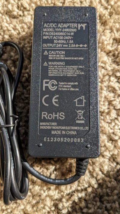
I have some new led's that I like but the cables going to the brick are really short and I really do not want the brick hanging off the tank. Not sure what they are thinking but 4ft is just way to short. The power brick is supplying 24v 2.5a via normal 5.5mm barrel connections and they make some 6ft extensions. I am aware of voltage drop but would the connections and 6ft really cause any issues, my guess is no but would like some others like @Sral @theatrus @oreo54 to weigh in. My other option is to replace the 24v power supplies with ones that have longer cables but thats not the cheap route, lol...I need about 10ft for one based on how i want to route the cords.

Navigation
Install the app
How to install the app on iOS
Follow along with the video below to see how to install our site as a web app on your home screen.
Note: This feature may not be available in some browsers.
More options
You are using an out of date browser. It may not display this or other websites correctly.
You should upgrade or use an alternative browser.
You should upgrade or use an alternative browser.
Extending 24v power for LED's
- Thread starter bishoptf
- Start date
- Tagged users None


- Joined
- Sep 18, 2017
- Messages
- 5,799
- Reaction score
- 3,567
Well depends on the wire size. If it isn't labeled on the wire on the brick it gets a bit more complicated.I have some new led's that I like but the cables going to the brick are really short and I really do not want the brick hanging off the tank. Not sure what they are thinking but 4ft is just way to short. The power brick is supplying 24v 2.5a via normal 5.5mm barrel connections and they make some 6ft extensions. I am aware of voltage drop but would the connections and 6ft really cause any issues, my guess is no but would like some others like @Sral @theatrus @oreo54 to weigh in. My other option is to replace the 24v power supplies with ones that have longer cables but thats not the cheap route, lol...I need about 10ft for one based on how i want to route the cords.
One method wold be to get an extension of known wire size and if you can't get the exact wire size off the brick just cut it short. A small section of undersized wire isn't critical or anything like a long section of undersized wire.
There are calculators but be aware that many are REALLY conservative.

DC Wire Size Calculator
Use our DC Wire Size Calculator to know the wire size needed for your DC electric application.
 www.omnicalculator.com
At 10ft one way (20 total, some calcs want this) and the extremely low voltage drop of 1%
16 Gauge wire will do.
20 ga @ 3%
for $15.29 (LRS 75-24) each you can buy a wire frame power supply and put whatever size wire you want on it.
As an added bonus you can adjust the output voltage to compensate for any resistance losses..
Up to 28.8V
")
Or even a large enough one to run multiple lights.
https://www.meanwell.com/webapp/product/search.aspx?prod=LRS-50&mws=841A95CBBDAA951E
Last edited:
OP
OP
Yeah the current wiring based on the sheathing states its 20awg, I was using this calc - https://www.inchcalculator.com/voltage-drop-calculator/ and got the same 3% for 20awg, 18awg was 1%. If I can find some 18awg extensions I think it should be fine. Yeah its an open shelf and Id rather not have something open frame etc...I need to do something like @theatrus brick solution but to lazy at the moment but I have lots of bricks, but some are 12v some are 24v and need to be able to turn them off individually etc...Well depends on the wire size. If it isn't labeled on the wire on the brick it gets a bit more complicated.
One method wold be to get an extension of known wire size and if you can't get the exact wire size off the brick just cut it short. A small section of undersized wire isn't critical or anything like a long section of undersized wire.
There are calculators but be aware that many are REALLY conservative.
DC Wire Size Calculator
Use our DC Wire Size Calculator to know the wire size needed for your DC electric application.
At 10ft one way (20 total, some calcs want this) and the extremely low voltage drop of 1%
16 Gauge wire will do.
20 ga @ 3%
for $15.29 (LRS 75-24) each you can buy a wire frame power supply and put whatever size wire you want on it.
As an added bonus you can adjust the output voltage to compensate for any resistance losses..
Or even a large enough one to run multiple lights.
https://www.meanwell.com/webapp/product/search.aspx?prod=LRS-50&mws=841A95CBBDAA951E

Should not be a massive problem, if you use wires with enough gauge (lower is betterI have some new led's that I like but the cables going to the brick are really short and I really do not want the brick hanging off the tank. Not sure what they are thinking but 4ft is just way to short. The power brick is supplying 24v 2.5a via normal 5.5mm barrel connections and they make some 6ft extensions. I am aware of voltage drop but would the connections and 6ft really cause any issues, my guess is no but would like some others like @Sral @theatrus @oreo54 to weigh in. My other option is to replace the 24v power supplies with ones that have longer cables but thats not the cheap route, lol...I need about 10ft for one based on how i want to route the cords.
) and do the connections right.You will get some voltage drop on the connections and the cables, which can in turn decrease your LED's power nonlinearly (if they are passively balanced and don't have a current driver inside the lamp). For passive balancing a 1% voltage drop will cause something like several % less maximum light output. If there is a constant current driver inside it will compensate for the losses up to the maximum of the supply.
As @oreo54 mentioned, 16 gauge will do.
Considering Wikipedia on AWG, it mentions 16 AWG having something like 4 mOhm / ft. 20ft total @ 2.5A gives you a drop of 0.2 V meaning 0.8% of your 24V.
18 AWG is an increase of about 60% resistance, so you will lose about 1.3% of yout total 24V instead.
Everything plus connection resistance and possibly bad solder/crimp joints of course, which adds maybe one or several inches of cable equivalent.
I remembered my lamp which I got from a small german manufacturer. I mentioned the cable size in my LED driver thread:Yeah the current wiring based on the sheathing states its 20awg, I was using this calc - https://www.inchcalculator.com/voltage-drop-calculator/ and got the same 3% for 20awg, 18awg was 1%. If I can find some 18awg extensions I think it should be fine. Yeah its an open shelf and Id rather not have something open frame etc...I need to do something like @theatrus brick solution but to lazy at the moment but I have lots of bricks, but some are 12v some are 24v and need to be able to turn them off individually etc...
it was 18AWG for each of the 6 channels, with two 18 AWG wires carrying the full 3.8A for about 8-10ft I think.
For a 6" piece on the dimmer the full 3.8A are even going over a single 18 AWG wire.
If you can stand the 1.3% voltage drop the 18AWG should work as well.
18AWG wire dissipates about 1 watt over 10ft (1.3% of 24V * 2.5A ~ 0.8W), heat dissipation to ambient is dominated by the interface to air ( typically 5W/meter^2/kelvin so let's use 7), so conservatively I would guesstimate a cable with 3mm diameter to warm to about 10°C, or 18°F above it's surrounding from that.
18AWG wire dissipates about 1 watt over 10ft (1.3% of 24V * 2.5A ~ 0.8W), heat dissipation to ambient is dominated by the interface to air ( typically 5W/meter^2/kelvin so let's use 7), so conservatively I would guesstimate a cable with 3mm diameter to warm to about 10°C, or 18°F above it's surrounding from that.

OP
OP
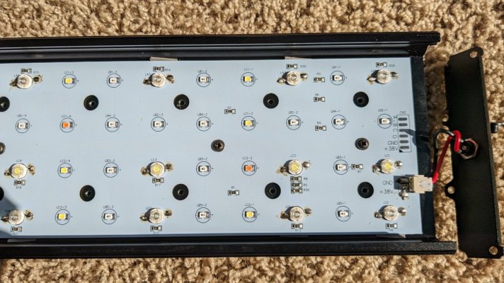
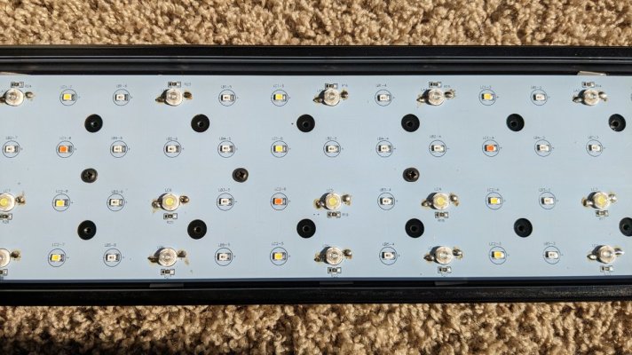
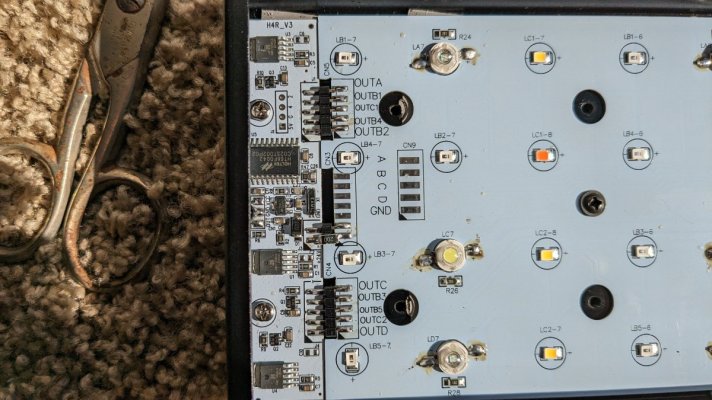
See attached pics, I can find 18awg and honestly think it would be fine but I have attached all of the gory detail pictures, its a pretty simple setup. Black Box shannon 50 reef led, or s50 reef led, they have been around for awhile and some bad press but I have nano tanks and they are shallow and could never find anything that I really liked and these I think are simple in operation and setup and IMHO do just fine. I would like to modify the moonlight channel with a couple of 6500k led's but we will see. Let me know what you see from the pics,
Attachments
-
 PXL_20240206_175039826.jpg256.4 KB · Views: 76
 -
 PXL_20240206_175658030.jpg193 KB · Views: 72
 -
 PXL_20240206_175701835.jpg185.9 KB · Views: 69
 -
 PXL_20240206_175721460.jpg143.7 KB · Views: 63
 -
 PXL_20240206_175711713.jpg183.4 KB · Views: 72
 -
 PXL_20240206_175727356.jpg153.6 KB · Views: 67
 -
 PXL_20240206_175742047.jpg143.4 KB · Views: 73
Well ... I see a lot of ICs. That makes me think "Constant Current Driver" or "onboard active voltage regulation", so I think the lamp itself will be fine and likely reach it's maximum intensity. We can research the specific ICs to see if I'm right, but I'm not sure if that's worth the effort.See attached pics, I can find 18awg and honestly think it would be fine but I have attached all of the gory detail pictures, its a pretty simple setup. Black Box shannon 50 reef led, or s50 reef led, they have been around for awhile and some bad press but I have nano tanks and they are shallow and could never find anything that I really liked and these I think are simple in operation and setup and IMHO do just fine. I would like to modify the moonlight channel with a couple of 6500k led's but we will see. Let me know what you see from the pics,
So the lamp will likely be fine and the cable likely as well. Although personally, I'd probably use at least 16 AWG wire, crimp or solder the ends and screw them into barrel connectors with screw terminals myself, just to sleep easy.
Something like this.
OP
OP
Yeah but if i go with the screw terminals i am having to cut the lines and splice. I can find some 18awg extensions but thats about as big as i can find. I want to replace soms of the leds, are there 24v leds, i purchased a spare to tinker around with, but the moonlight channel is all blue and i would like a couple soft whites in there.Well ... I see a lot of ICs. That makes me think "Constant Current Driver" or "onboard active voltage regulation", so I think the lamp itself will be fine and likely reach it's maximum intensity. We can research the specific ICs to see if I'm right, but I'm not sure if that's worth the effort.
So the lamp will likely be fine and the cable likely as well. Although personally, I'd probably use at least 16 AWG wire, crimp or solder the ends and screw them into barrel connectors with screw terminals myself, just to sleep easy.
Something like this.
The light has 4 channels,
10k white, i believe 3w
moonlight
blue channel 3w led
65k white with a few red, low wattage led
controlled with a ir remote, has a bunch of timer options, which i think is some of the circuity. I will do some more pics to get more of an idea of the layout.

Well, you could just extend the previous barrel connectors with another, right ? Not sure how it looks like currently , but you could just plug a female barrel one into the male from the power supply and use a male on the other side for the lamp, if I'm not mistaken.Yeah but if i go with the screw terminals i am having to cut the lines and splice. I can find some 18awg extensions but thats about as big as i can find. I want to replace soms of the leds, are there 24v leds, i purchased a spare to tinker around with, but the moonlight channel is all blue and i would like a couple soft whites in there.
The light has 4 channels,
10k white, i believe 3w
moonlight
blue channel 3w led
65k white with a few red, low wattage led
controlled with a ir remote, has a bunch of timer options, which i think is some of the circuity. I will do some more pics to get more of an idea of the layout.
OP
OP
Yup that is what I was wanting to do exactly, they have them in 18awg but I see in 14awg but much longer than needed. I took some measurements, looks like the 3w leds fully dimmed are .077v and full brightness go to 3.1v and the smaller leds start around 2.5v and go up to 3v. I need to double check those but they should be in the ballpark. So they are controlling the voltage with one of the IC's based on the channel via the remote, 24.3v I read coming into the unit.Well, you could just extend the previous barrel connectors with another, right ? Not sure how it looks like currently , but you could just plug a female barrel one into the male from the power supply and use a male on the other side for the lamp, if I'm not mistaken.
I will annotate a diagram with which led's go to which channel...

OP
OP
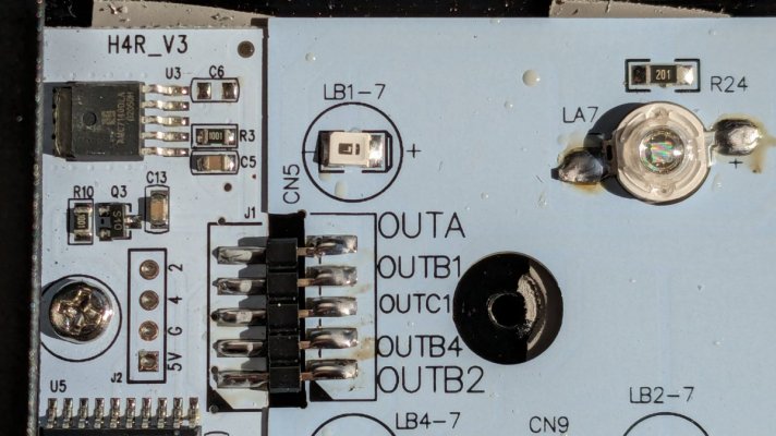
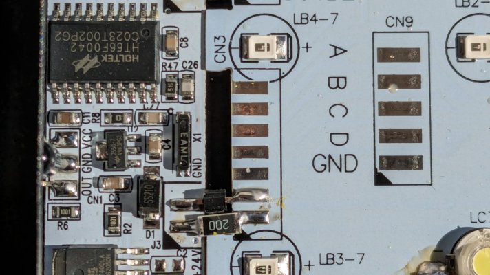
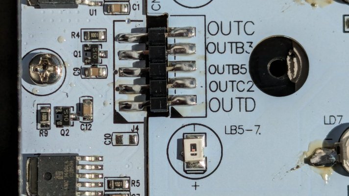
Here is the channel layout, there are 4 channels on the remote like I specified and they are color coded in this picture, Red, yellow, purple, and blue. But if you look closer to the green blocks there appears to be sub channels, looks like they split those channels 10 ways. In the green bocks you will see that they have outA, outB1, outC1, outB4, outB2, outC, outB3, outB5, outC2 and outD. If you notice on each led they call out an led sequence that corresponds to the input in the green box. For the blue channel its la and ld for the 3w leds and then, lb1, lb3, lb4 and lb5, for the other leds on the same channel which is channel 3. Not sure I understand why they do that is what they are doing.
Channel1 white 10k 3w - LC:1-7
Channel2 Moonlight - LB2:1-7
Channel3 Combo, 3w Blue LA and LD, blue and green leds LB1, LB3, LB4 and LB5
Channel4 natural white and red 65K -LC1 and LC2


Channel1 white 10k 3w - LC:1-7
Channel2 Moonlight - LB2:1-7
Channel3 Combo, 3w Blue LA and LD, blue and green leds LB1, LB3, LB4 and LB5
Channel4 natural white and red 65K -LC1 and LC2

I'll have a look if I can figure out what your text means tomorrow. Too tired right now ^^Here is the channel layout, there are 4 channels on the remote like I specified and they are color coded in this picture, Red, yellow, purple, and blue. But if you look closer to the green blocks there appears to be sub channels, looks like they split those channels 10 ways. In the green bocks you will see that they have outA, outB1, outC1, outB4, outB2, outC, outB3, outB5, outC2 and outD. If you notice on each led they call out an led sequence that corresponds to the input in the green box. For the blue channel its la and ld for the 3w leds and then, lb1, lb3, lb4 and lb5, for the other leds on the same channel which is channel 3. Not sure I understand why they do that is what they are doing.
Channel1 white 10k 3w - LC:1-7
Channel2 Moonlight - LB2:1-7
Channel3 Combo, 3w Blue LA and LD, blue and green leds LB1, LB3, LB4 and LB5
Channel4 natural white and red 65K -LC1 and LC2
My though is that they might have balanced each line to have roughly 21 V nominal voltage (~7*3V) and probably both controllers to out roughly the same current in total, or at least stay below max current.
My guess would also be that the current going through a line of big blue LEDs is larger than the current going through a line of colored smaller LEDs.
OP
OP
No problem I just like to try to understand, I am going to pull come voltages off of it later this evening for each of the outputs.I'll have a look if I can figure out what your text means tomorrow. Too tired right now ^^
My though is that they might have balanced each line to have roughly 21 V nominal voltage (~7*3V) and probably both controllers to out roughly the same current in total, or at least stay below max current.
My guess would also be that the current going through a line of big blue LEDs is larger than the current going through a line of colored smaller LEDs.


- Joined
- Sep 18, 2017
- Messages
- 5,799
- Reaction score
- 3,567
The drivers are linear regulators. They've used them in most models. Had the chip info at one time but.. gone.Well ... I see a lot of ICs. That makes me think "Constant Current Driver" or "onboard active voltage regulation", so I think the lamp itself will be fine and likely reach it's maximum intensity. We can research the specific ICs to see if I'm right, but I'm not sure if that's worth the effort.
So the lamp will likely be fine and the cable likely as well. Although personally, I'd probably use at least 16 AWG wire, crimp or solder the ends and screw them into barrel connectors with screw terminals myself, just to sleep easy.
Something like this.
Dsuny and Popbloom
That's the old model.
Anyways the channel labeling is a bit odd but I assume they need to split them a bit so as to not overheat the driver ic's with too large of a voltage drop.
New ones are err "prettier"..but same linear drivers.
Actually this was an older model..
I'll see if I can find the driver number.
For now pretend its a CAT4101
OK.. took longer than expected..
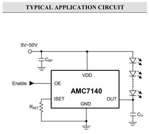
Pretty sure this is the driver IC, at least for some models.
ADDtek
AMC7140
Last edited:
OP
OP
Thats a different model called the turing, has a different controller and is a higher wattage unit with a fan, I believe that one is 100w this one is 60w no fan. I believe it has more 3w leds (maybe all 3w leds) but with my shallow tanks I did not need the power, it has enough 3w leds and a bunch of low watt leds. Its fine for my shallow tanks and I believe more simple design, really a much simpler layout. I am interested in why they have things split up like they have, has 4 channels but on the board it has the circuits split across 10 paths, you can see that from my picture above. I would also like to identify the types of low power leds, i would like to replace a couple blues with natural white on the moon channel so it doesnt make it all blue but a touch of white to go along with the 7 blues. I need to take some voltage measurements which I haven't done yet but would like to understand more how its working though.The drivers are linear regulators. They've used them in most models. Had the chip info at one time but.. gone.
Dsuny and Popbloom
That's the old model.
Anyways the channel labeling is a bit odd but I assume they need to split them a bit so as to not overheat the driver ic's with too large of a voltage drop.
New ones are err "prettier"..but same linear drivers.

Actually this was an older model..

I'll see if I can find the driver number.
For now pretend its a CAT4101
OK.. took longer than expected..
Pretty sure this is the driver IC, at least for some models.
ADDtek
AMC7140
- Joined
- Sep 18, 2017
- Messages
- 5,799
- Reaction score
- 3,567
My guess was because of using linear drivers. They need each string to be as close to 24v ( your power supply) or the drivers can over heat dropping too much voltage.And of course can't exceed 24v.Thats a different model called the turing, has a different controller and is a higher wattage unit with a fan, I believe that one is 100w this one is 60w no fan. I believe it has more 3w leds (maybe all 3w leds) but with my shallow tanks I did not need the power, it has enough 3w leds and a bunch of low watt leds. Its fine for my shallow tanks and I believe more simple design, really a much simpler layout. I am interested in why they have things split up like they have, has 4 channels but on the board it has the circuits split across 10 paths, you can see that from my picture above. I would also like to identify the types of low power leds, i would like to replace a couple blues with natural white on the moon channel so it doesnt make it all blue but a touch of white to go along with the 7 blues. I need to take some voltage measurements which I haven't done yet but would like to understand more how its working though.
The Turing and Shannon actually refer to the type of controller.
The Turing controller was the first one from the DSunY data.
The no fan varieties just run the diodes at a lower current at least that was my understanding from the past.
Btw my 2 photos are 2 different models.
Last edited:

yeah, each of that chip can only take maybe 4-8Wof heat dissipation, before it derates and shuts down or lowers the current, depending on how well it is cooled.My guess was because of using linear drivers. They need each string to be as close to 24v ( your power supply) or the drivers can over heat dropping too much voltage.And of course can't exceed 24v.
The Turing and Shannon actually refer to the type of controller.
The Turing controller was the first one from the DSunY data.
The no fan varieties just run the diodes at a lower current at least that was my understanding from the past.
Btw my 2 photos are 2 different mode
The problem isn’t the dropped voltage though, but the thus dissipated power:
- at full power the controllers have little voltage to drop, but takes the full current. Loss Power is low, e.g. 1V*2.5A~2.5W
- at low power, the controllers have the most voltage to drop, but the LEDs decrease the current massively. Loss power is low, e.g. 6V*0.2A~1.2W
In between there is a maximum, as the controllers drop a moderate voltage and the LEDs still allow a moderate current, e.g.
3V*1.25A~3.75W
It all depends on the steepness of the LED‘s current vs voltage curve. If the LEDs are almost off already at 18V (as I have assumed above) the driver takes little loss power. If they are already off at a higher voltage, Loss power drops further and Vice versa, if the LEDs only drop out at a lower voltage, the Loss power on the chip increases.
Last edited:
OP
OP
Here are all the channel layouts, I still need to take some measurements and I am calling the small led 1w but not sure what the rating is for them, just that they look like strip led lights.
led number, wattage, channel color, channel number
LA:1-7,3w, Blue, Ch3
LC:1-7,3w, 10K White, Ch1
LD:1-7,3w, Blue, Ch3
LB1:1-7,1w, Blue, Ch3
LB2:1-7,1w, Blue, Ch3
LB3:1-7,1w, Blue, Ch3
LB4:1-7,1w, Moon, Ch2
LB5:1-7,1w, Blue, Ch3
LC1:1-8,1w, 65k Nwhite, Ch4
LC2:1-7,1w, 65k Nwhite, Ch4
Will take some voltage measurements and add them to the mix..
Similar threads
- Replies
- 2
- Views
- 88
- Replies
- 7
- Views
- 127
New Posts
-
 HELP ! Trouble keeping fish alive
- Latest: vetteguy53081
-

-

-
-


