Extending 24v power for LED's

oreo54

5000 Club Member
View Badges
Joined
Sep 18, 2017
Messages
5,604
Reaction score
3,450
Rating - 0%
0   0   0
Here are all the channel layouts, I still need to take some measurements and I am calling the small led 1w but not sure what the rating is for them, just that they look like strip led lights.

led number, wattage, channel color, channel number
LA:1-7,3w, Blue, Ch3
LC:1-7,3w, 10K White, Ch1
LD:1-7,3w, Blue, Ch3
LB1:1-7,1w, Blue, Ch3
LB2:1-7,1w, Blue, Ch3
LB3:1-7,1w, Blue, Ch3
LB4:1-7,1w, Moon, Ch2
LB5:1-7,1w, Blue, Ch3
LC1:1-8,1w, 65k Nwhite, Ch4
LC2:1-7,1w, 65k Nwhite, Ch4

Will take some voltage measurements and add them to the mix..
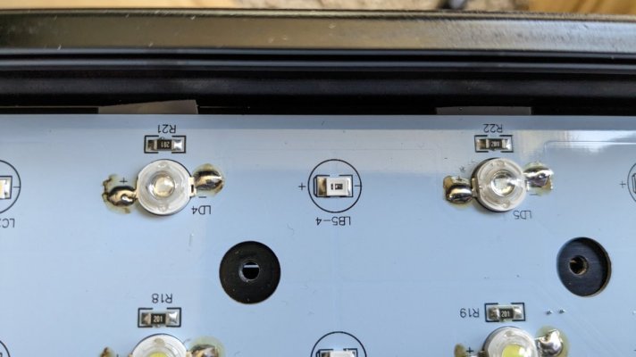
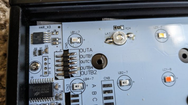
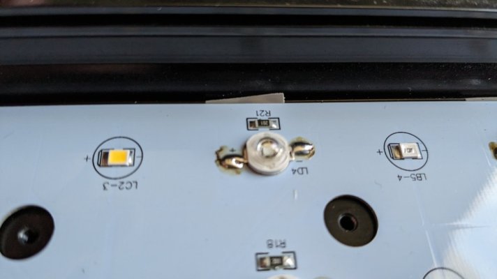
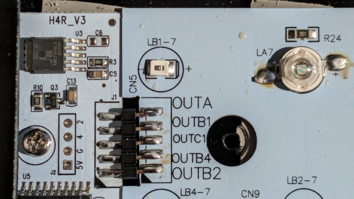
Funny... I believe they did run the fanless ones around 350mA which would make sense at 24V
 
OP
OP
bishoptf

bishoptf

Valuable Member
View Badges
Joined
Jan 1, 2019
Messages
1,345
Reaction score
1,722
Location
Missouri
Rating - 0%
0   0   0
Here is some odd stuff, so I am taking measurements at OutB2 for the LB2 channel which is channel 2 moon lights, has 7 small leds. at off it reads 8.2v and then the first step up is 6.2v on the other end at 100% it reads .006v, 90% is .369v, 80% is .95v.

This is kind of confusing to me since I would think it would be the opposite, anyone explain what is going on?
 

Attachments

  • PXL_20240206_175721460.jpg
    PXL_20240206_175721460.jpg
    143.7 KB · Views: 47

oreo54

5000 Club Member
View Badges
Joined
Sep 18, 2017
Messages
5,604
Reaction score
3,450
Rating - 0%
0   0   0
Here is some odd stuff, so I am taking measurements at OutB2 for the LB2 channel which is channel 2 moon lights, has 7 small leds. at off it reads 8.2v and then the first step up is 6.2v on the other end at 100% it reads .006v, 90% is .369v, 80% is .95v.

This is kind of confusing to me since I would think it would be the opposite, anyone explain what is going on?
Oh thanks..you got a good shot at one of the drivers..
popbloomdriver.JPG

1000 Ohms, hmmm

They dim them by using the enable pin as a switch.
PWM voltage is variable and no listing of use-able frequency.

Bit for reference..somewhat more confusing than helpful ;).
2)dimming protocal is 3V-12V in light to support many kind of PWM signal.
dimming protocal is 3V in Turing v1 , 6V turing V2.
3) PWM.
1). if you mean light panel control signal.(dimming protocal ) NO, we never useing linear IC driver. from the first board ,it is PWM
if you mean the power of the controller. it is buck (DC 24/36V input)

Please the power should be much careful .
in Turing, the power is come from the light. (24V or 36V ). the buck to 3V (V1) or 5V (v2) to MCU.
in GHL/Apex , seems they only accept 12V.
1, so it is impossible drive them from the light.
2, so driver it using it own power.
3, connect the GND togeter .
 
Last edited:

Sral

Valuable Member
View Badges
Joined
May 2, 2022
Messages
1,006
Reaction score
976
Location
Germany
Rating - 0%
0   0   0
Here is some odd stuff, so I am taking measurements at OutB2 for the LB2 channel which is channel 2 moon lights, has 7 small leds. at off it reads 8.2v and then the first step up is 6.2v on the other end at 100% it reads .006v, 90% is .369v, 80% is .95v.

This is kind of confusing to me since I would think it would be the opposite, anyone explain what is going on?
The IC is a low side driver. It is basically:
24V to LED to driver to GND

The higher the voltage on the driver the less voltage drops over the LEDs, leading to less current and light.
 

Sral

Valuable Member
View Badges
Joined
May 2, 2022
Messages
1,006
Reaction score
976
Location
Germany
Rating - 0%
0   0   0
Oh thanks..you got a good shot at one of the drivers..
popbloomdriver.JPG

1000 Ohms, hmmm


They dim them by using the enable pin as a switch.
PWM voltage is variable and no listing of use-able frequency.

Bit for reference..somewhat more confusing than helpful ;).
1000 Ohms would mean 600mA max per driver. Sounds reasonable, at maximum this means about 0.3A *4V ~ 2W at the driver.

When mounted on a PCB the chip can dissipate that with about 40C or 72F above its ambient
 
OP
OP
bishoptf

bishoptf

Valuable Member
View Badges
Joined
Jan 1, 2019
Messages
1,345
Reaction score
1,722
Location
Missouri
Rating - 0%
0   0   0
The IC is a low side driver. It is basically:
24V to LED to driver to GND

The higher the voltage on the driver the less voltage drops over the LEDs, leading to less current and light.
Ah, hmm thats interesting way of doing things. So here are the 4 channels via the led board

Channel 1 10K white, 7 3w leds (so they say but it does look more blue white) LC
PXL_20240208_171936961.jpg

Channel 2 - Moonlight 7 (small leds, not sure power) LB4
PXL_20240208_171927769.jpg

Channel 3 - Blue, 14 3w leds (LA,LD), 21 blue small leds (LB1,LB2,LB3,LB5), 7 green leds (total 14 3w, 28 small leds)
PXL_20240208_171916350.jpg

Channel 4 65K natural white w/ red, 12 65k small, 4 red small, 16 total LC1 and LC2
PXL_20240208_171853979.jpg


Not sure the low power leds put out any par but more for looks, although the 65K whites get pretty bright vs the blue leds. Not sure why I am posting all this but maybe someone may be interested to see the layout. :)
 
OP
OP
bishoptf

bishoptf

Valuable Member
View Badges
Joined
Jan 1, 2019
Messages
1,345
Reaction score
1,722
Location
Missouri
Rating - 0%
0   0   0
1000 Ohms would mean 600mA max per driver. Sounds reasonable, at maximum this means about 0.3A *4V ~ 2W at the driver.

When mounted on a PCB the chip can dissipate that with about 40C or 72F above its ambient
It appears the 3 watt the pcb board is cut out around the leds and there is some thermal tape that is attached behind the 3w leds going to the enclosure/heat sink.

Attached some pics close up of the 3w and the thermal stuff, one pic you can see it oozing around one of the screw holes....
 

Attachments

  • PXL_20240208_191011955.jpg
    PXL_20240208_191011955.jpg
    91.9 KB · Views: 52
  • PXL_20240208_191054914.jpg
    PXL_20240208_191054914.jpg
    135.7 KB · Views: 46
  • PXL_20240208_191027244.jpg
    PXL_20240208_191027244.jpg
    70.7 KB · Views: 22
OP
OP
bishoptf

bishoptf

Valuable Member
View Badges
Joined
Jan 1, 2019
Messages
1,345
Reaction score
1,722
Location
Missouri
Rating - 0%
0   0   0
Got some cables in, 6.5ft second go around, first ones i ordered the wrong tip size. These are 18awg and while I could find some larger guage they were all much longer than i needed. With the original adapter cable length at full power reading from board i get 24.07v. with the extended cable I am getting 23.85v. Looks like the drop is about .25v, brightness looks the same, hard to say but at 100% they are pretty bright so it would be hard to say if they are the same. Either way I am not goimg to be running them at 100% so I think this should be fine.
 

Sral

Valuable Member
View Badges
Joined
May 2, 2022
Messages
1,006
Reaction score
976
Location
Germany
Rating - 0%
0   0   0
Got some cables in, 6.5ft second go around, first ones i ordered the wrong tip size. These are 18awg and while I could find some larger guage they were all much longer than i needed. With the original adapter cable length at full power reading from board i get 24.07v. with the extended cable I am getting 23.85v. Looks like the drop is about .25v, brightness looks the same, hard to say but at 100% they are pretty bright so it would be hard to say if they are the same. Either way I am not goimg to be running them at 100% so I think this should be fine.
Nice, 0.3V is about 1.2%, funny how accurate the calculation was :grinning-face-with-sweat:
 

Reefing threads: Do you wear gear from reef brands?

  • I wear reef gear everywhere.

    Votes: 36 16.3%
  • I wear reef gear primarily at fish events and my LFS.

    Votes: 13 5.9%
  • I wear reef gear primarily for water changes and tank maintenance.

    Votes: 1 0.5%
  • I wear reef gear primarily to relax where I live.

    Votes: 28 12.7%
  • I don’t wear gear from reef brands.

    Votes: 129 58.4%
  • Other.

    Votes: 14 6.3%
Back
Top