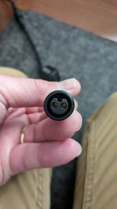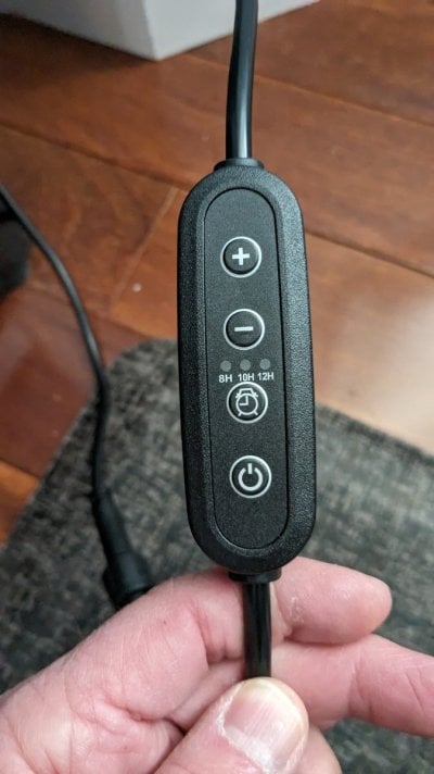

I have controlled 12v led lights before with a N-chaneel mosfet and feed pwm from reef-pi but would like someone to tell me if this would work the same way. I have some led light strips, they are 24vdc input and they have an inline dimmer, see attached pics. The power supply is a 2amp 24v dc power supply. I hooked up my multimeter to the dimmer and looks like low is 13.5v and as you increase the brightness the voltage increases up to 24v. Could I use the same n-lever mosfet to control these lights but feeding 12v vs 12v? What I am thinking is in this case in reef-pi I would set the minimum threshold to say 60% so the range would start around 13v and go up to 24v. Am is missing anything or does that sound logically and should work?
@Sral @theatrus or anyone see any issues with doing that?
Thanks and Happy New Year everyone!


@Sral @theatrus or anyone see any issues with doing that?
Thanks and Happy New Year everyone!

")