Phlizon 165W PWM Light Control

avar2005

New Member
View Badges
Joined
Aug 18, 2021
Messages
16
Reaction score
22
Location
Canada
Rating - 0%
0   0   0
Full disclosure, I barely know what I'm doing, but after sleuthing the forums I've clobbered something together that works for me.

Parts used:
2x Phlizon 165W Dimmable Full Spectrum Aquarium LED Lights (No WiFi, just dumb lights)
Raspberry pi 4B
Raspberry Pi Prototyping Board HAT by MakerSpot
LM2596 Buck Converter
22 AWG wire
Old Dell Laptop power supplies that got sacrificed for the project (19.5V / 3.34A)

The reason for the project was to gain control of the individual channels, as well as be able to ramp up / down the channels individually on a schedule. I was turning the lights on (both blue and white) at the same time without ramp time with a smart outlet (I'm still using the smart outlet, read below).

I did a poor job of taking pictures during the build, but I'll share what I have.

The internals (credit to BRS Black Box LED Battle Royale as I didnt snap a pic while working on it):
1645562600552.png


The Blue and White channels are controlled by two of these:
1645562752713.png


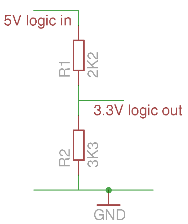
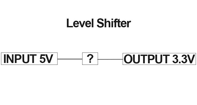
Conveniently, they are PWM and 3.3V.

I left the main power to the drivers as is, and wired the 3.3V, PWM and GND for the White Channel drivers to GPIO 18. and The same for the Blue Channel drivers to GPIO 19.

The main hitch I ran into is that the fans are controlled separately from the lights by this 12V driver. So even with the LEDs off, the fans spin away happily.
6BE34FEF-2F88-458A-9214-0F5A839F3EC9_1_201_a.jpg


My ghetto solution right now is to use a smart outlet and turn the lights on / off just before the ramp-up and ramp-down timers come on.

Finished Product:
ReefPi Screenshot.jpg

I've had this running for just about a week, and it's been solid. I need to 3D print a larger case for the Pi, and maybe a little case for the buck converter, but other than that I'm pretty happy with it.

IMG_3860.jpg
 

robsworld78

Well-Known Member
View Badges
Joined
Feb 14, 2020
Messages
952
Reaction score
1,281
Location
Edmonton, Canada
Rating - 0%
0   0   0
Thanks for sharing this!
Newbie here with a Phlizon LED black box and a Robo-Tank setup.

Asking any Version 1 Controller Robo-Tank users if we would need to use the LM2596 Buck Converter to step down the signal before wiring into GPIO 18 and 19 sockets?

Thanks!

John

@robsworld78
Unfortunately the 3.3v volt signal required by the drivers is a little difficult on the controller as the PWM outputs have been converted to 5v signals as not many things use 0v-3.3v PWM.

With that said GPIO18 is used for Sensor port 4 but you can tap into it before being converted on the sensor extension. You know the jumpers that you set to select which plug to use for each port, it has a row of 3 header pins and just above that row is a single header pin in the middle. If you don't add any jumpers you can connect to the middle pin on the 3 pin header which is GPIO18 untouched so you could run a jumper from it to a driver and control. These are the header pins I'm referring to.


GPIO19 isn't quite as easy as that's being used for outlet 7 on power bar 1. If you have an AC power bar you could move it to power bar 2 DB9 and run a wire from outlet 7 pin on the main controller. At that stage it's straight from the Pi. Here's the pinout of the DB9 so you can see which pin is outlet 7.


As for needing the LM2596 I'm unsure as I don't know where that's being used, it might just be part of the build.
 

oreo54

5000 Club Member
View Badges
Joined
Sep 18, 2017
Messages
5,608
Reaction score
3,451
Rating - 0%
0   0   0
As for needing the LM2596 I'm unsure as I don't know where that's being used, it might just be part of the build.
Driver states the white wire is outputting 3.3v.... is that correct?
In which case can't one use a
MOSFET with the 5v pwm to the gate?

To be honest can you " switch" 3.3v w/ a 5v gate voltage?
I can't follow the below answer...


Of course this Philzon with 5v pwm dimming is a different driver than the above ..

https://www.reef2reef.com/threads/black-box-leds-how-to-control-with-apex-vdm.944756/

Sooo first question is " which Philzon driver"?
 
Last edited:

robsworld78

Well-Known Member
View Badges
Joined
Feb 14, 2020
Messages
952
Reaction score
1,281
Location
Edmonton, Canada
Rating - 0%
0   0   0
Driver states the white wire is outputting 3.3v.... is that correct?
In which case can't one use a
MOSFET with the 5v pwm to the gate?

To be honest can you " switch" 3.3v w/ a 5v gate voltage?
I can't follow the below answer...


Of course this Philzon with 5v pwm dimming is a different driver than the above ..

https://www.reef2reef.com/threads/black-box-leds-how-to-control-with-apex-vdm.944756/

Sooo first question is " which Philzon driver"?
I believe the driver in the picture above has an input voltage of 3.3v for the white wire, that's probably why the LM2596 was used as there was no 3.3v available. As you pointed out the different drivers in some of these lights I guess that needs to be verified by @jory88.

As this is connecting to my controller he could get 3.3v from the feeder port. The messy part is needing 3.3v PWM, at least that's what I'm thinking it is, as the controller is setup for 5v PWM so you have to tap in to other parts of the controller which makes it a little messy with wires coming from all over but it should work.
 

Sral

Valuable Member
View Badges
Joined
May 2, 2022
Messages
1,006
Reaction score
976
Location
Germany
Rating - 0%
0   0   0
You could try any port that puts out a 5V PWM signal or a 12V PWM signal (like on the DC ports) and step it down using two resistors. For 5 V you would need a ~2:3 ratio ( like 4.7k and 9.6k) and for 12V you need a ~7:2 ratio ( like 9.6k and 2.7k).

Otherwise a n-MOSFET with a resistor to 3.3V will also work, even when applying a 5V PWM to the gate.
 

robsworld78

Well-Known Member
View Badges
Joined
Feb 14, 2020
Messages
952
Reaction score
1,281
Location
Edmonton, Canada
Rating - 0%
0   0   0
You could try any port that puts out a 5V PWM signal or a 12V PWM signal (like on the DC ports) and step it down using two resistors. For 5 V you would need a ~2:3 ratio ( like 4.7k and 9.6k) and for 12V you need a ~7:2 ratio ( like 9.6k and 2.7k).

Otherwise a n-MOSFET with a resistor to 3.3V will also work, even when applying a 5V PWM to the gate.
So you can use a voltage divider to step down the PWM? I was wondering about that but forgot to ask. I was thinking a mosfet had to be used.
 

oreo54

5000 Club Member
View Badges
Joined
Sep 18, 2017
Messages
5,608
Reaction score
3,451
Rating - 0%
0   0   0
You could try any port that puts out a 5V PWM signal or a 12V PWM signal (like on the DC ports) and step it down using two resistors. For 5 V you would need a ~2:3 ratio ( like 4.7k and 9.6k) and for 12V you need a ~7:2 ratio ( like 9.6k and 2.7k).

Otherwise a n-MOSFET with a resistor to 3.3V will also work, even when applying a 5V PWM to the gate.

resistive-logic-downshifter.png

Warning: This method works for slow signals, but it’s not very reliable.

 
Last edited:

Sral

Valuable Member
View Badges
Joined
May 2, 2022
Messages
1,006
Reaction score
976
Location
Germany
Rating - 0%
0   0   0
So you can use a voltage divider to step down the PWM? I was wondering about that but forgot to ask. I was thinking a mosfet had to be used.
Hmm, it definitely works for the outputs of the PCA9685, if the resistors are at least 2k.

Now that you mention it, it might not work well with the DC ports. I‘d have to look at the circuit diagrams. Do you have one for the v1 controller ready ?
 

robsworld78

Well-Known Member
View Badges
Joined
Feb 14, 2020
Messages
952
Reaction score
1,281
Location
Edmonton, Canada
Rating - 0%
0   0   0
Hmm, it definitely works for the outputs of the PCA9685, if the resistors are at least 2k.

Now that you mention it, it might not work well with the DC ports. I‘d have to look at the circuit diagrams. Do you have one for the v1 controller ready ?
They would need to be large resistors to handle any kind of load, for DC ports it's easier to put an adjustable regulator on the output and set it to the max voltage needed.
 

Sral

Valuable Member
View Badges
Joined
May 2, 2022
Messages
1,006
Reaction score
976
Location
Germany
Rating - 0%
0   0   0
They would need to be large resistors to handle any kind of load, for DC ports it's easier to put an adjustable regulator on the output and set it to the max voltage needed.
Since we were interested in generating a 3.3V PWM signal that doesn’t need to drive any kind of load, that sounds like it might be beside the point. The regulator might be an interesting idea, although I don’t know how well regulators react when you feed them a chopped PWM voltage. Might lead to unexpected behavior.

What I was mostly getting at in the context of the DC ports is that they are n-MOSFET switched, meaning when it’s off, the voltage on both contacts becomes 12V relative to RoboTank GND. So one would need to be careful with how one connects the step down resistors and takes the signal off them.
 

robsworld78

Well-Known Member
View Badges
Joined
Feb 14, 2020
Messages
952
Reaction score
1,281
Location
Edmonton, Canada
Rating - 0%
0   0   0
Since we were interested in generating a 3.3V PWM signal that doesn’t need to drive any kind of load, that sounds like it might be beside the point. The regulator might be an interesting idea, although I don’t know how well regulators react when you feed them a chopped PWM voltage. Might lead to unexpected behavior.

What I was mostly getting at in the context of the DC ports is that they are n-MOSFET switched, meaning when it’s off, the voltage on both contacts becomes 12V relative to RoboTank GND. So one would need to be careful with how one connects the step down resistors and takes the signal off them.
The DC ports are designed to be a PWM signal, they are just for DC devices that's why I mentioned the regulator. For example if a person had 24v and 12v devices they could power up the DC extension with 24v so all the DC ports put out 24v and can then add a DC regulator on the output of a DC port so it only has a maximum of 12v or whatever is needed.

If someone needs a PWM or analog signal they can use the PWM/analog ports. Like in this case 3.3v PWM is needed so it would be best to use a 5v PWM output and add the voltage divider so it's a maximum of 3.3v PWM.
 

Sral

Valuable Member
View Badges
Joined
May 2, 2022
Messages
1,006
Reaction score
976
Location
Germany
Rating - 0%
0   0   0
The DC ports are designed to be a PWM signal, they are just for DC devices that's why I mentioned the regulator. For example if a person had 24v and 12v devices they could power up the DC extension with 24v so all the DC ports put out 24v and can then add a DC regulator on the output of a DC port so it only has a maximum of 12v or whatever is needed.

If someone needs a PWM or analog signal they can use the PWM/analog ports. Like in this case 3.3v PWM is needed so it would be best to use a 5v PWM output and add the voltage divider so it's a maximum of 3.3v PWM.
The regulator could work, but that’s still an if, as long as nobody has tried that in my opinion, since not every regulator has to react well to a chopped input voltage.

What I was saying in regards to the resistor step-down is that one needs to be careful, since otherwise the signal can become 12V (or whatever voltage one feeds the system) relative to system GND.

Another idea: „just“ use an ESP32 inside the lamp, if you can power it there with ease. It directly puts out 3.3V PWM and can connect to ReefPi over WiFi
 

Reefing threads: Do you wear gear from reef brands?

  • I wear reef gear everywhere.

    Votes: 47 16.8%
  • I wear reef gear primarily at fish events and my LFS.

    Votes: 18 6.5%
  • I wear reef gear primarily for water changes and tank maintenance.

    Votes: 1 0.4%
  • I wear reef gear primarily to relax where I live.

    Votes: 35 12.5%
  • I don’t wear gear from reef brands.

    Votes: 159 57.0%
  • Other.

    Votes: 19 6.8%
Back
Top