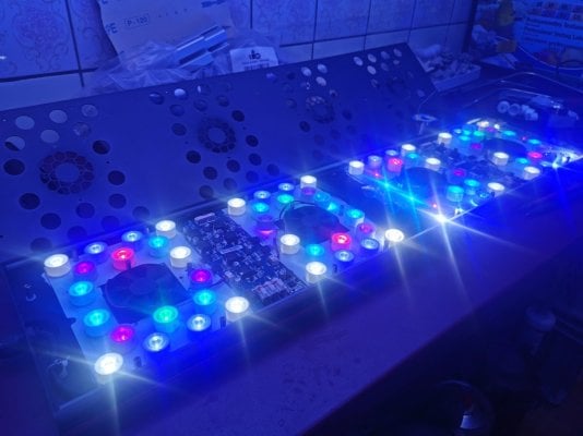
Pi with Evergrow IT2040 (Black Box)

biojo

New Member
View Badges
Joined
Apr 3, 2017
Messages
11
Reaction score
2
Rating - 0%
0   0   0
Im looking at connecting my Pi to 2 Evergrow IT2040 these are generic black box, with digital interface on front

1712830575324.png

I dont have any pics of the PCB, but the inside has 2 large drivers, to power white / blue and the fans, and a small one to power the moon lights

1712830703154.png


I believe the lights drivers are PWM controlled, I have seen some where they opperate in reverse 100% is off etc
But wome say 2 wires need to be turned on to activate the driver, sme i have seen use a relay, others suggest this is perm connected, but does this consume more electric? or is there a down side

Also the documentation on reef pi looks fairly simple to make, but then others have said add a capacitor?

just after some clear guidance on where to start

thanks
 

Ranjib

7500 Club Member
View Badges
Joined
Apr 16, 2016
Messages
9,843
Reaction score
17,058
Location
Pleasant Hill, Concord
Rating - 0%
0   0   0
I have never played with black boxes, I’ll recommend with starting without capacitor and see if there’s flickering, and then add capacitor if need be
 

yury88

Active Member
View Badges
Joined
Oct 21, 2023
Messages
115
Reaction score
79
Location
indo-pacific
Rating - 0%
0   0   0
4 wires are going to each driver.
For PWM it should be 2-wire.

It can easily can be some interface like SPI or custom made, so no way to use reef-pi.
Better to make pcb photo in high-resolution one of the driver or use Oscilloscope
 

Lukes Saltwater Tank

New Member
View Badges
Joined
Dec 7, 2022
Messages
18
Reaction score
10
Location
Germany
Rating - 0%
0   0   0
Hi, im not sure if it is of relivance for your project but I have just finished and am documenting my Reef-pi light build. Its for the evergrow IT5040/80 or Photon lights. Are you trying to design a new controller or use the old one with reef-pi?

Here is the Intro video to my project where you can get an over view of what its about:
 
OP
OP
B

biojo

New Member
View Badges
Joined
Apr 3, 2017
Messages
11
Reaction score
2
Rating - 0%
0   0   0
I have never played with black boxes, I’ll recommend with starting without capacitor and see if there’s flickering, and then add capacitor if need be
What type of capacitor would it be and is this just on the out put pwm if its needed
4 wires are going to each driver.
For PWM it should be 2-wire.

It can easily can be some interface like SPI or custom made, so no way to use reef-pi.
Better to make pcb photo in high-resolution one of the driver or use Oscilloscope

4 wires to each driver, so what are each one used for, I guessing

GND
+V (10v? to power the board)
a signal to turn on and off the driver?
the PWM signal

My plan was to use a PCA9685 , in combination with a Pi, I have already wrote all code to output the PWM via the normal pins on the Pi

Hi, im not sure if it is of relivance for your project but I have just finished and am documenting my Reef-pi light build. Its for the evergrow IT5040/80 or Photon lights. Are you trying to design a new controller or use the old one with reef-pi?

Here is the Intro video to my project where you can get an over view of what its about:


To disconnect the control panel on the front of the existing lights, and have it controlled via a schedule in python

So far i have this

1713526764113.png


You basically tell it a start time, max whites, max blues, how long moons to stay on
Start =12:00
MaxWhite = 15%
MaxBlue = 90%
MoonsAfter = 0:30

So for the values above, the lights come on at 12:00 and turn off at 24:00, but the light gradually come on in a curve so at 18:00 there at 15% and 90%,

1713527046515.png


after 12:00, the moons remain on for 30 minutes and gradually decrease to 0
 

yury88

Active Member
View Badges
Joined
Oct 21, 2023
Messages
115
Reaction score
79
Location
indo-pacific
Rating - 0%
0   0   0
4 wires to each driver, so what are each one used for, I guessing

GND
+V (10v? to power the board)
a signal to turn on and off the driver?
the PWM signal
Controller on same power source with driver, so no reason for extra wires for powering.
But its all just guessing, i suggest to open driver and make some high resolution photos because without understanding architecture its just wasting of time...

More likely that driver using digital potentiometer for current control, thats why it can be more than 2 wires
 
OP
OP
B

biojo

New Member
View Badges
Joined
Apr 3, 2017
Messages
11
Reaction score
2
Rating - 0%
0   0   0
I thought I had a picture of the board as I checked when I was replacing the fans last year, but Im sure the PCB tracks where labelled with PWM

yeah I wanted to use the power coming out of the driver, if its 12/10v to up the 5V pwm to 10V
 

Lukes Saltwater Tank

New Member
View Badges
Joined
Dec 7, 2022
Messages
18
Reaction score
10
Location
Germany
Rating - 0%
0   0   0
So i finished uploading the videos of my Reef-pi project, not sure if there is anything that could help you achive you goals but thought i would share anyhow.

If the PCB does have the PWM pins labeled as Biojo says then it would actually be quite easy to build a similar circuit to run reef-pi.

here are my videos: Click here for videos
 

Attachments

  • IMG_20240331_232942.jpg
    IMG_20240331_232942.jpg
    127.7 KB · Views: 11
OP
OP
B

biojo

New Member
View Badges
Joined
Apr 3, 2017
Messages
11
Reaction score
2
Rating - 0%
0   0   0
Cheers I've watched them all already lol

Yeah someone had similar lights in past and they had same labels as mine, but says to join 2 wires to turn on the driver, so they used a relay, others i read said just to join them, but i dont know if this then consumes any more power.

I too will be designing a pcb, done this is past for 4x doser, temp controller, ATU
 

oreo54

5000 Club Member
View Badges
Joined
Sep 18, 2017
Messages
5,619
Reaction score
3,456
Rating - 0%
0   0   0
People still messing with these weird drivers huh .
Anyways there is probably a decade of work on them.
A deep dive and opening one of the driver cases to see what's written on the circuit board will aid you.
Apex, Aduino..all been done before.

Automating the old manual ones makes sense.
Since they are only 2 channels re-automating to a different control interface. Well fine but seems more time consuming than worthwhile.
Just my opinion and therefore worth little.

Anyways it's all been answered before I'm sure.
 

Just grow it: Have you ever added CO2 to your reef tank?

  • I currently use a CO2 with my reef tank.

    Votes: 2 3.4%
  • I don’t currently use CO2 with my reef tank, but I have in the past.

    Votes: 2 3.4%
  • I have never used CO2 with my reef tank, but I plan to in the future.

    Votes: 4 6.9%
  • I have never used CO2 with my reef tank and have no plans to in the future.

    Votes: 47 81.0%
  • Other.

    Votes: 3 5.2%
Back
Top