Reef Pi Compatible Lighting

pseudorand

Well-Known Member
View Badges
Joined
Oct 29, 2019
Messages
641
Reaction score
439
Rating - 0%
0   0   0
Does anyone have hints on figuring out if a lighting solution is compatible with Reef Pi Lighting controller? Obviously the Kessil models listed in the article will work, but I'd like to buy a cheaper light to start just to get familiar with how it works. I'm also not 100% I'm putting a reef in my new 120g. I may do freshwater and I'd prefer not to spend $1k on lights if I don't actually need them for corals or plants. I want to use Reef Pi to get a gradual day/night cycle in any case because I want to see how my fish do at dawn and dusk.

I suppose it at least has to plug in to a 2.1mm barrel from the parts list, but that info isn't typically in the spec sheet when you're buying lights online. Or perhaps you cut and re-wire the cord to plug into that, but that's also something I'd prefer not to do to a $300 light, at least not until I've done it once before and know how it works.
 

Ranjib

7500 Club Member
View Badges
Joined
Apr 16, 2016
Messages
9,843
Reaction score
17,058
Location
Pleasant Hill, Concord
Rating - 0%
0   0   0
Welcome to reef2reef :0)

Folks have tried MarsAqua, Reefbrite, viparspectra etc, if I recall correctly. But definitely lot more than kessil. In fact I think I am the only one I know of running kessil :)

reef-pi is a fixed software, and the hardware/circuit part is something each of us build by ourself (mostly, unless you are using that hats/pcbs etc). Which means depending upon your light you can build the appropriate circuit. Most DIY lights should be directly powered by meanwell drivers. which can be controlled be reef-pi.

Check out this page for some examples: https://reef-pi.github.io/additional-documentation/resources/
 

burningbaal

Active Member
View Badges
Joined
Aug 13, 2019
Messages
232
Reaction score
257
Location
Near Seattle
Rating - 0%
0   0   0
Related to the OP here (hopefully this isn't a hijack, just another angle at the same question):
There are dozens of cheap led fixtures that take a DC input. some are dimmable and some are not. Is there a relatively straightforward concept to follow? I have 3 or 4 (two are daisy-chainable) DC LED fixtures that have their own wall wart, but it would be nice to just feed each DC from the reef-pi, potentially with no dimming since it's ill-defined for cheap ebay fixtures (I don't even know what the lights I'm using are they seem unique and I know they were cheap, all I have is my old ebay email that described the item as 50/50 Aquarium LED Light 40W 12000K white/Actinic Blue (Metal Halide alt.) Reef). Also some DCV LED strips.

anyways, is there a basic idea we can follow? If we confirm the voltage input (by checking the output of the power supply), ensure we're delivering that voltage at the defined power (in my case, 2x20W at 48DCV)...is there a walkthrough of wiring 'your' lights for the reef-pi (and configuring it)?
 

oreo54

5000 Club Member
View Badges
Joined
Sep 18, 2017
Messages
5,640
Reaction score
3,472
Rating - 0%
0   0   0
Generally if you start w/ fw lights most of the err "budget" brands run constant voltage.
Budget level Currents, Finnex,Beamsworks, and assorted similar led "boards".
This is usually a global thing i.e no channel control though there are complicated ways of splitting channels but the
"converter' circuits usually become more complicated as well.

If simple constant voltage arrays all one needs to do is use a suitable MOSFET to switch the feed voltage on and off.
Simplistic image but any digital output pin will work. Of course one needs to consider the load/voltage on the MOSFET.

basic_pwm.png


since the pi outputs a digital signal it just needs to feed a digital mosfet ..

Constant current arrays will need to be handled different depending on the driver dimming protocol.
Most common ones are 5V PWM (actually can vary from 3.3 to 6-ish)
10V PWM (not sure of the headroom here, older Meanwells were said to not like >10V to the point of burning out the dim circuitry),
0-10 or 1-10V analog, Prob. the most complicated since one needs to go from digital to analog.
But that's worked out w/ the Kessil circuit.

and last simple "pot" dimming..

Many drivers are "multi" types though like 10v PWM OR 0-10 analog OR pot

Each will require different circuitry except those w/ 3.3V PWM dim circuits.
Meanwell LDD-H's are an example but those don't really come w/ your lights in general.
Those can be driven directly from the digital out pins ..
Plenty of Aduino examples of this

Of course lights with built in controllers are another story altogether..or boards w/ drivers "on board" which is getting a bit more common...

Best to sort of pick a light then ask really..
 

Bigtrout

Valuable Member
View Badges
Joined
Dec 16, 2018
Messages
1,189
Reaction score
2,826
Rating - 0%
0   0   0
Does anyone have hints on figuring out if a lighting solution is compatible with Reef Pi Lighting controller? Obviously the Kessil models listed in the article will work, but I'd like to buy a cheaper light to start just to get familiar with how it works. I'm also not 100% I'm putting a reef in my new 120g. I may do freshwater and I'd prefer not to spend $1k on lights if I don't actually need them for corals or plants. I want to use Reef Pi to get a gradual day/night cycle in any case because I want to see how my fish do at dawn and dusk.

I suppose it at least has to plug in to a 2.1mm barrel from the parts list, but that info isn't typically in the spec sheet when you're buying lights online. Or perhaps you cut and re-wire the cord to plug into that, but that's also something I'd prefer not to do to a $300 light, at least not until I've done it once before and know how it works.
If you dont do a reef and just do freshwater, i have fairly easily controlled 2 beamswork f-spec DA lights. Bright enough for most plants, not good for a reef but at 60 bux for a 48 inch light, with reef pi controlling it its like a 200 dollar freshwater plant light.
 
OP
OP
pseudorand

pseudorand

Well-Known Member
View Badges
Joined
Oct 29, 2019
Messages
641
Reaction score
439
Rating - 0%
0   0   0
reef-pi is a fixed software, and the hardware/circuit part is something each of us build by ourself (mostly, unless you are using that hats/pcbs etc). Which means depending upon your light you can build the appropriate circuit. Most DIY lights should be directly powered by meanwell drivers. which can be controlled be reef-pi.

Thanks for the reply. I think what I really need is a tutorial on electrical circuitry and LED lighting. Any resources you recommend?
 

Ranjib

7500 Club Member
View Badges
Joined
Apr 16, 2016
Messages
9,843
Reaction score
17,058
Location
Pleasant Hill, Concord
Rating - 0%
0   0   0
Thanks for the reply. I think what I really need is a tutorial on electrical circuitry and LED lighting. Any resources you recommend?
There are some really good YouTube videos on this topic. Search with diy lighting for reef or fresh water. The plot is pretty common, you get or assemble the light then hook up a meanwell driver and control the driver with a pwm board. Circuit details are covered on these tutorials
 
OP
OP
pseudorand

pseudorand

Well-Known Member
View Badges
Joined
Oct 29, 2019
Messages
641
Reaction score
439
Rating - 0%
0   0   0
I just bought this, not for the tank but for my cabinet. It's got barrel connectors and is supposedly dimmable. I'm going to try to wire it to control it through my Reef Pi -- should that be possible? If not, why not?

At that price it should make for a good dry run. If I get it working, I may even wire up a switch that turns the lights on from dim to bright when I open one of the cabinet doors. There's probably simpler ways to do that than Reef PI, but if I can figure out how to do that I can figure out the expensive lights for the tank.
 

oreo54

5000 Club Member
View Badges
Joined
Sep 18, 2017
Messages
5,640
Reaction score
3,472
Rating - 0%
0   0   0
I just bought this, not for the tank but for my cabinet. It's got barrel connectors and is supposedly dimmable. I'm going to try to wire it to control it through my Reef Pi -- should that be possible? If not, why not?

At that price it should make for a good dry run. If I get it working, I may even wire up a switch that turns the lights on from dim to bright when I open one of the cabinet doors. There's probably simpler ways to do that than Reef PI, but if I can figure out how to do that I can figure out the expensive lights for the tank.

Constant voltage strips.. Easy peasy..

breadboard.png


ONE can just buy the needed circuit..
 

Bigtrout

Valuable Member
View Badges
Joined
Dec 16, 2018
Messages
1,189
Reaction score
2,826
Rating - 0%
0   0   0
Constant voltage strips.. Easy peasy..

breadboard.png


ONE can just buy the needed circuit..
Thats how i controlled my beamsworks, only the leds are common cathode so they required mosfet modules that used p channel mosfets.
 
OP
OP
pseudorand

pseudorand

Well-Known Member
View Badges
Joined
Oct 29, 2019
Messages
641
Reaction score
439
Rating - 0%
0   0   0
Thanks to everyone for all the replies so far. I have the lights and the Pi, but I've been busy building a stand and re-sealing my tanks, so I haven't tried it yet.

Constant voltage strips.. Easy peasy..

How do you know those are constant voltage strips from the Amazon posting? And what's the significance of constant voltage? Are constant-voltage controllers that limit amperage to dim the lights cheap and common or something? (Note that my experience with electrical is high school physics 20 years ago, so please forgive my ignorance it that made no sense.)

And what's a MOSFET? I just read wikipedia and I still don't get it. The reef-pi guide says to choose the right "transistor or power MOSFET", and I'm a bit at a loss about how to do that.

That's for the MOSFET recommendation for the lights I bought, but I'm also interested in understanding why that particular product would work. What pieces of info on that e-bay posting are you looking at to know it's compatible with the lights I bought?
 

oreo54

5000 Club Member
View Badges
Joined
Sep 18, 2017
Messages
5,640
Reaction score
3,472
Rating - 0%
0   0   0
MOSFET is nothing but a high speed switch..
Turning a light on/off at say 50% on 50% off is PWM dimming.

W/ constant voltage strips (most small ones are and some larger) use constant voltage and teminating resistors on a string to control current..
MOSFET just turns the power off and on.

Normally a 5V(3.3V) PWM (5v on 5v off) signal is applied to the gate of the MOSFET. This drives the same on/off to the power supply..

Transistors can be uses in sort of the same way..

anyways simple MOSFET diagram.

5 (or 3.3v both the most common) positive charge is apllied to the gate..allowing stopping or starting the circuit to the LED
basic_pwm.png


Normally there is, in the case of 12V constant voltage, a string of 3 leds in series plus a resistor to "regulate" current..
Then a bunch of these are in parallel..but best get first things first..

since most logic signals are positive one uses a NPN Mosfet (technically better anyways) but most strip type lights use a negative ground you can't easily split the channels..but global dimming is easy.

As to your lights eactly.. see the 3 diodes plus one component? tell-tale in general.
Also know how the dimmer works for the most part.
And no "driver" just a switching power supply of 12 volts..
 
Last edited:
OP
OP
pseudorand

pseudorand

Well-Known Member
View Badges
Joined
Oct 29, 2019
Messages
641
Reaction score
439
Rating - 0%
0   0   0
Constant voltage strips.. Easy peasy..

breadboard.png


ONE can just buy the needed circuit..

I don't think I properly thanked you for the custom circuit design. Thanks!

A few more questions as I'm getting back to this project:

1) Do I understand correctly that the design in the drawing above with the NPN transistors is one way to do it and buying a Power MOSFET is a different way? The transistors and the circuit in the drawing would be like the circuit for the Kessels in the reef-pi lighting controller and the MOSFET would be like the actinic LED strip in the reef-pi lighting controller, correct?

2) Why are there two NPN transistor circuits in your drawing above? I think the under-cabinet strip lights I bought just have one channel, so I would just need one, correct? I should expect to find just two wires if I opened up one of the barrel connectors, right?

3) If I use the MOSFET, I should just need 1 x 1k resistor connected in series with the GATE pin and I wouldn't need the second 10k resistor, correct?

4) The MOSFET source pin goes to the -Ve of barrel connector/lights and the MOSFET drain pin goes to ground, correct? In the article, I think the text is correct but the diagram with the mint tin proto board has it backwards. The datasheet shows the pinout at G-D-S but in the drawing in the article, the middle pin is going to the barrel connector and the rightmost pin is going to ground.
 

oreo54

5000 Club Member
View Badges
Joined
Sep 18, 2017
Messages
5,640
Reaction score
3,472
Rating - 0%
0   0   0
I don't think I properly thanked you for the custom circuit design. Thanks!

A few more questions as I'm getting back to this project:

1) Do I understand correctly that the design in the drawing above with the NPN transistors is one way to do it and buying a Power MOSFET is a different way? The transistors and the circuit in the drawing would be like the circuit for the Kessels in the reef-pi lighting controller and the MOSFET would be like the actinic LED strip in the reef-pi lighting controller, correct?

2) Why are there two NPN transistor circuits in your drawing above? I think the under-cabinet strip lights I bought just have one channel, so I would just need one, correct? I should expect to find just two wires if I opened up one of the barrel connectors, right?

3) If I use the MOSFET, I should just need 1 x 1k resistor connected in series with the GATE pin and I wouldn't need the second 10k resistor, correct?

4) The MOSFET source pin goes to the -Ve of barrel connector/lights and the MOSFET drain pin goes to ground, correct? In the article, I think the text is correct but the diagram with the mint tin proto board has it backwards. The datasheet shows the pinout at G-D-S but in the drawing in the article, the middle pin is going to the barrel connector and the rightmost pin is going to ground.

first, not my circuits.. Best I do is "tinker-toy" modules.
I'll let the electronics gurus do the heavy lifting..

Kessil dims w/ 0-10 applied to their dim circuitry on their internal drivers.
Strips, in general just cut the power on/off rapidly to appear dimmer..
Kessils probably do the same thing just not here. They could dim w/ lowing current but not as common anymore as PWM

MOSFETS are THE common part to control on/off high current circuits.
Most dim circuits are low current circuits.

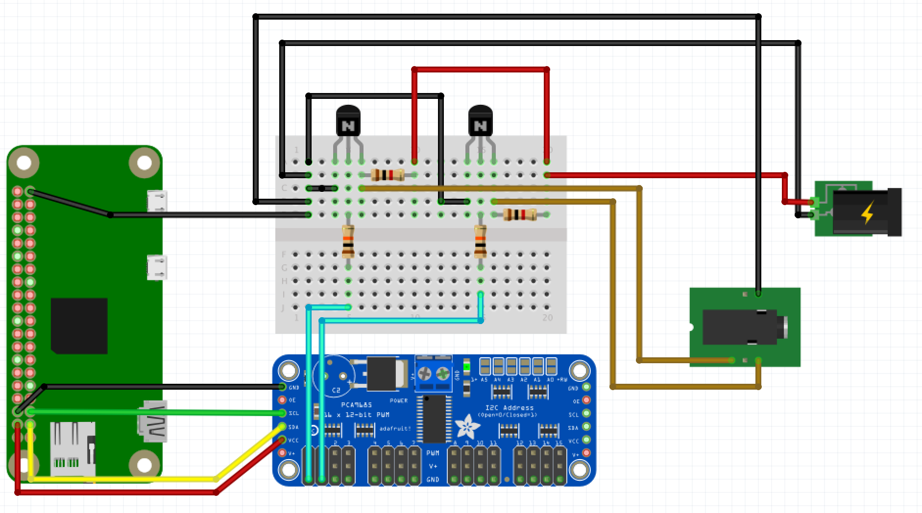
The picture has 2 transistors because the Kessil has 2 channels..

This is what you would basically use per channel on strip lights.
Ignore 'M" and diode ...and just substitute led strip.

motor%20MOSFET_low_side_driver.png


And:
 
Last edited:

reefin_with_the_fam

Active Member
View Badges
Joined
Oct 19, 2019
Messages
150
Reaction score
147
Rating - 0%
0   0   0

Michael Lane

Well-Known Member
View Badges
Joined
Aug 11, 2018
Messages
677
Reaction score
1,123
Rating - 0%
0   0   0
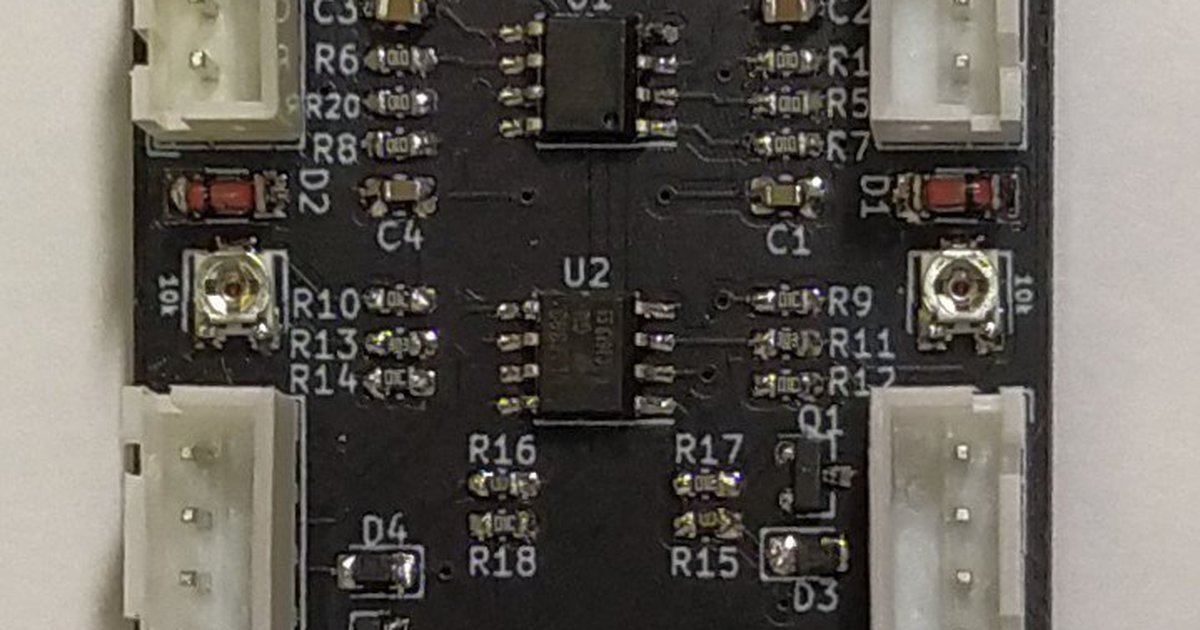
I make that board. It can work with reef-pi or arduino (or almost anything that generates a PWM signal). It's made specifically for Mars Aqua lights. The cables to the knobs in the light plug into the 2 bottom connectors (4 pins). The 3 pin connector at the top accepts 2 pwm signals and ground. The other 3 pin lets you daisy chain the signal to more lights if you want.

My build thread for this board is here. I have 8 lights running on them.
 
OP
OP
pseudorand

pseudorand

Well-Known Member
View Badges
Joined
Oct 29, 2019
Messages
641
Reaction score
439
Rating - 0%
0   0   0
So I finally got around to hooking up the under-cabinet lights I'm using for testing to reef-pi and oreo5457 was right: easy peasy.

Now that I'm basically an electrical engineer :), I'm ready to buy my real lights. Does anyone know what makes the expensive reef lights better? If it's just spectrum and intensity:
  • Spectrum: Won't any 3-channel/RGB LED let me set the spectrum to whatever I like?
  • Intensity: Won't lots of smaller LEDs (such as strip lighting) provide the same intensity as one big one, while also alleviating spotlight effects?
Is there something besides spectrum and intensity that makes the expensive reef lights different? (Don't say control, reef-pi will give me that.)

For the sake of posterity, I just used the moonlight part of the circuit from the Reef Pi lighting guide. I stripped out the parts for the Kessel, including the PCA9685 board, since I only needed one PWM signal and the PI has two built-in. The two things that threw me for a bit were:

  1. Common 5v and 12v ground.
    Apparently that's fine. If they had separate grounds, it would be more clear to us novices that you really have two circuits.
    * The 12v is a loop of wire between the power source and the light with the source and drain pins of the MOSFET completing part of the circuit.
    * The 5V is a loop of wire that connects one of the PI's PWM pins back to a ground pin. The MOSFETs gate pin just needs to touch that circuit to read the signal.

  2. What's the resistor for?
    There is a 10k resistor in series as part of the 5v circuit, but I think that's optional. It's there to provide pull-down protection. (Note: I didn't try my circuit sans the resistor.)
 

Freshwater filter only or is it? Have you ever used an HOB filter on a saltwater tank?

  • I currently use a HOB filter on my reef tank.

    Votes: 50 25.3%
  • I don’t currently use a HOB filter on my reef tank, but I have in the past.

    Votes: 50 25.3%
  • I have used a HOB on fish only or quarantine tanks, but not on the display tank.

    Votes: 46 23.2%
  • I have never used a HOB on a saltwater tank.

    Votes: 48 24.2%
  • Other.

    Votes: 4 2.0%
Back
Top