Reef-Pi The All In One Pi Challenge

crusso1993

7500 Club Member
View Badges
Joined
Oct 21, 2018
Messages
8,671
Reaction score
44,647
Location
SW, FL, USA
Rating - 0%
0   0   0
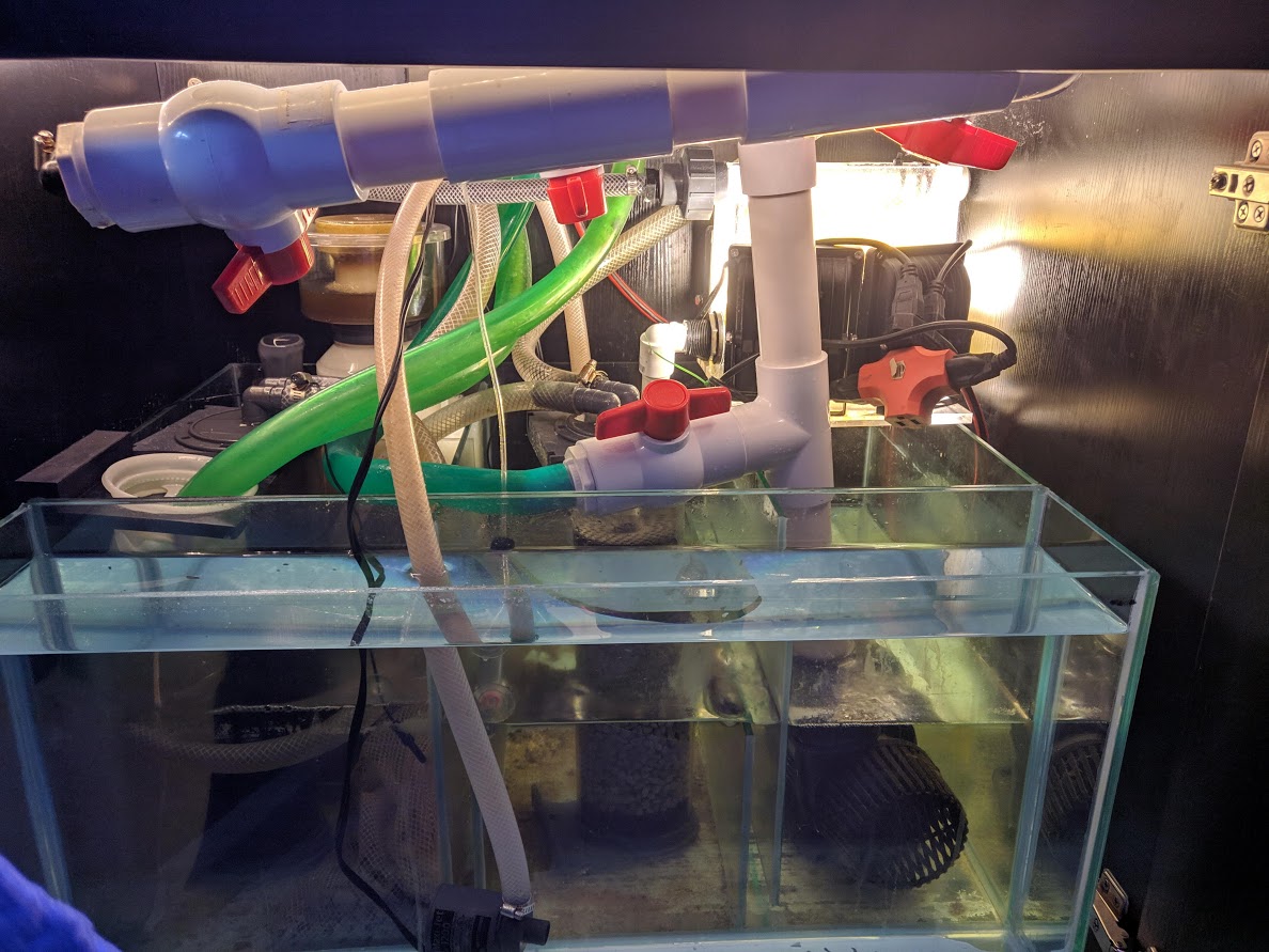
"Safe" lol so is putting 24 plugs into 1 plug acceptable? The other plug is my chiller. My old house has like no working plugs. I have 2 working outlets in this room. And the other outlet is my 1200W PC and 450W 3d printer as well as many other devices. Unfortunately when I'm gaming on my PC and 3d printing I trip the breaker. But yeah it's super safe see the pic LOL
IMG_20190504_232752.jpg

OH I forgot to mention water.

I had to look away!
 
OP
OP
AquaRaider44

AquaRaider44

#Reef4Life
View Badges
Joined
Apr 19, 2019
Messages
526
Reaction score
822
Location
Brevard County
Rating - 0%
0   0   0
I had to look away!
I do too sometimes :D
No, "safe" as in you put the outlets into a real electrical box.
As far as the under the stand pic goes....well...
That's next to the tank where the fish splash water :D I hope to build a vented cabinet there soon for the chiller and plugs. Under the stand is filled with every imaginable piece of filtration equipment.
V34cDUB_2-bPv58A44S5EP0yVNCWgrkLGfJaZUpWEZhfPlaP0r_WmL06u5xevznwiIRvP-EyyTGpsWm3Zwt93BqR18wzNtUY5cNCl6BGOnb0PpscVLdsMSH2ptjUfNlOGPNgWxcgkiwCONCrYon1Ug73xwdYJ-W0aQWagUACXa6_LATud7AeflaL2TW4lrLGf-gk18FTjR4gfJKQv160hw-T2nGe4QL8Ykfz0IInTgDj4C797BelO69S03x_vsE0FTK846abB4Jpyb7NiKhYVO8HPoSQoVbVnQNldTpeapYrdCX9w7obYuZrvReh1PDsmilMXB2Soq7Iv-DA6AjfLOYulACE7qjXk35v3fk8mtumtZFn_m4aVpWJRPTe0-NDYY0hKiDmYy51EMfiFQ7QciNloxh7ziINguoRmqmRmA9k7sEkpyRhnwmh4IjviGMPPaFmpZTH7M-LeeQSg7NGujZ56_TkoEHlooF5jw7jYVrgqpPHUye3ShU5qxUWUImW5VemRs--Zn2bS6flEjKX5QewqJNn6w1_95jJiWagYTDF_oJxcniB5YdoVceyxJSiwV3mjNPP_ZE_0uJrOwEVhx7sb5gljHBEmMXSQlhgsd3e9k51Ym1SvYmhZVLmK30ULV0BMpmfBUQ01mz5FSxp51FbsgsAYNo_=w1188-h891-no
 

Ranjib

7500 Club Member
View Badges
Joined
Apr 16, 2016
Messages
9,843
Reaction score
17,058
Location
Pleasant Hill, Concord
Rating - 0%
0   0   0
Quick update new buck converters arrived today and worked like a charm and you can't hear them at all. I think the old ones were knockoffs as they were total **** quality and were fluctuating voltage.
Glad it was the buck converter .
 

Michael Lane

Well-Known Member
View Badges
Joined
Aug 11, 2018
Messages
677
Reaction score
1,123
Rating - 0%
0   0   0
Just got my jeabo dp4s dosing pumps and float switches but am still waiting on the 1k resistors. I do need some help understanding how I can use the dp4s as is. It has like a phone cable to use @Michael Lane
IMG_20190510_151310.jpg
IMG_20190510_151258.jpg
That looks pretty much like the DP3S.
The easiest approach would be to provide 12v over the cable, with the motor control lines connected to a ULN2803. Then you could control the pumps with either binary GPIO or a PWM signal.

I did something similar, so I can pop mine open tomorrow and take a look at the board to provide more specific information.
 
OP
OP
AquaRaider44

AquaRaider44

#Reef4Life
View Badges
Joined
Apr 19, 2019
Messages
526
Reaction score
822
Location
Brevard County
Rating - 0%
0   0   0
That looks pretty much like the DP3S.
The easiest approach would be to provide 12v over the cable, with the motor control lines connected to a ULN2803. Then you could control the pumps with either binary GPIO or a PWM signal.

I did something similar, so I can pop mine open tomorrow and take a look at the board to provide more specific information.
I would appreciate that thank you. I already have the PCA9685 Breakout board. What would be the easiest way to connect to this? Is this just signal and I need to provide power too or will the PCA9685 Breakout board provide power? It has a telephone cable with 6 lines in it to provide 12v power and ground and signals I think but I am not sure. Could I just connect this wire to power and the PCA9685 Breakout board?
 

Michael Lane

Well-Known Member
View Badges
Joined
Aug 11, 2018
Messages
677
Reaction score
1,123
Rating - 0%
0   0   0
The PCA9685 is definitely only going to provide a signal. You'll need another component in the middle to use that signal and control the motors. You don't want to connect the pca9685 directly to the RJ11 connector. You should use something like the following diagram. Your board is laid out a bit differently than mine, but the connector is probably the same as what I have, but you should double check with a meter to be sure. For me, pin 1 and 6 are 12v, and the others are for control signal.
upload_2019-5-11_18-55-5.png


Or maybe like this if you are using a breadboard
upload_2019-5-11_18-57-0.png


My board
 
OP
OP
AquaRaider44

AquaRaider44

#Reef4Life
View Badges
Joined
Apr 19, 2019
Messages
526
Reaction score
822
Location
Brevard County
Rating - 0%
0   0   0
The PCA9685 is definitely only going to provide a signal. You'll need another component in the middle to use that signal and control the motors. You don't want to connect the pca9685 directly to the RJ11 connector. You should use something like the following diagram. Your board is laid out a bit differently than mine, but the connector is probably the same as what I have, but you should double check with a meter to be sure. For me, pin 1 and 6 are 12v, and the others are for control signal.
upload_2019-5-11_18-55-5.png


Or maybe like this if you are using a breadboard
upload_2019-5-11_18-57-0.png


My board
How can they both be 12v? Does this mean the pwm signals are the ground off the 9685?
 

Michael Lane

Well-Known Member
View Badges
Joined
Aug 11, 2018
Messages
677
Reaction score
1,123
Rating - 0%
0   0   0
They are both 12v possibly to just distribute the current since it is going over a cable. The PCA9685 turns on the ULN2803, which will allow the current to flow to ground.
 
OP
OP
AquaRaider44

AquaRaider44

#Reef4Life
View Badges
Joined
Apr 19, 2019
Messages
526
Reaction score
822
Location
Brevard County
Rating - 0%
0   0   0
They are both 12v possibly to just distribute the current since it is going over a cable. The PCA9685 turns on the ULN2803, which will allow the current to flow to ground.
Ok cool that makes total sense. I'm not sure which two are power here though. See pics. I assume it's the two with the fancy symbol. And blue and white in the cable which are the outside two.

IMG_20190511_192238.jpg


IMG_20190511_192304_1.jpg
 

theatrus

Valuable Member
View Badges
Joined
Mar 26, 2016
Messages
1,955
Reaction score
3,355
Location
Sacramento, CA area
Rating - 0%
0   0   0
Ok cool that makes total sense. I'm not sure which two are power here though. See pics. I assume it's the two with the fancy symbol. And blue and white in the cable which are the outside two.

IMG_20190511_192238.jpg


IMG_20190511_192304_1.jpg


The two outermost cables are tied together. Usually when you see large planes, you can assume the original designer assumed this was the GND plane.

It looks like @Michael Lane 's schematic has those two lines connected to 12V (since the ULN is a low side driver). This will work, but the LEDs on the front panel will not work if this is backwards from the original design. The DC motors and ceramic capacitors/resistors on the little breakout board don't care which way they are connected :)
 
OP
OP
AquaRaider44

AquaRaider44

#Reef4Life
View Badges
Joined
Apr 19, 2019
Messages
526
Reaction score
822
Location
Brevard County
Rating - 0%
0   0   0
The two outermost cables are tied together. Usually when you see large planes, you can assume the original designer assumed this was the GND plane.

It looks like @Michael Lane 's schematic has those two lines connected to 12V (since the ULN is a low side driver). This will work, but the LEDs on the front panel will not work if this is backwards from the original design. The DC motors and ceramic capacitors/resistors on the little breakout board don't care which way they are connected :)
How would I hook it up so that the LEDs would work?
 

Michael Lane

Well-Known Member
View Badges
Joined
Aug 11, 2018
Messages
677
Reaction score
1,123
Rating - 0%
0   0   0
@theatrus is right about copper planes usually being ground. In this case, I believe the original design intended it to be 12v. The LEDs on my doser still light up when the motor is active.

It's easy to test if you have a 12v power supply (especially if you can limit to current). Just apply 12v, and connect one of the signal pins to ground. The motor should spin and the LED should light.
 

theatrus

Valuable Member
View Badges
Joined
Mar 26, 2016
Messages
1,955
Reaction score
3,355
Location
Sacramento, CA area
Rating - 0%
0   0   0
@theatrus is right about copper planes usually being ground. In this case, I believe the original design intended it to be 12v. The LEDs on my doser still light up when the motor is active.

It's easy to test if you have a 12v power supply (especially if you can limit to current). Just apply 12v, and connect one of the signal pins to ground. The motor should spin and the LED should light.

Perfect - was trying to visually trace from the pictures but might have misidentified what’s where. :)
 
OP
OP
AquaRaider44

AquaRaider44

#Reef4Life
View Badges
Joined
Apr 19, 2019
Messages
526
Reaction score
822
Location
Brevard County
Rating - 0%
0   0   0
@theatrus is right about copper planes usually being ground. In this case, I believe the original design intended it to be 12v. The LEDs on my doser still light up when the motor is active.

It's easy to test if you have a 12v power supply (especially if you can limit to current). Just apply 12v, and connect one of the signal pins to ground. The motor should spin and the LED should light.
Perfect - was trying to visually trace from the pictures but might have misidentified what’s where. :)

Quick update I confirmed the pins and stuff and built the circuit and am just waiting for the ULN2803 which will be here tomorrow.
 

stefanm

Active Member
View Badges
Joined
Oct 11, 2017
Messages
360
Reaction score
397
Location
Sweden
Rating - 0%
0   0   0
I use a dp4s on my reef-pi, the outer two pins are grounds and the others are for the +ve on the pumps 1-4, I used supplied cable into an rj45 socket then connected to l239d ready made modules, cheaper and much easier than building circuits on proto boards.

I also use separate psu's, one for the pi, pca9685 and l239d's another 5 volt for the relay board and one 12volt for the doser. Every lm module I have gives exact same output as the input, so I binned them. Also I didn't have the patience or inclination to build any of Ranjib's circuits, especially when you can by them ready made for penny's.
 
OP
OP
AquaRaider44

AquaRaider44

#Reef4Life
View Badges
Joined
Apr 19, 2019
Messages
526
Reaction score
822
Location
Brevard County
Rating - 0%
0   0   0
I use a dp4s on my reef-pi, the outer two pins are grounds and the others are for the +ve on the pumps 1-4, I used supplied cable into an rj45 socket then connected to l239d ready made modules, cheaper and much easier than building circuits on proto boards.

I also use separate psu's, one for the pi, pca9685 and l239d's another 5 volt for the relay board and one 12volt for the doser. Every lm module I have gives exact same output as the input, so I binned them. Also I didn't have the patience or inclination to build any of Ranjib's circuits, especially when you can by them ready made for penny's.
Since you had them as grounds do the LEDs light us I'm pretty sure they are 12v
 

Rock solid aquascape: Does the weight of the rocks in your aquascape matter?

  • The weight of the rocks is a key factor.

    Votes: 10 8.7%
  • The weight of the rocks is one of many factors.

    Votes: 42 36.5%
  • The weight of the rocks is a minor factor.

    Votes: 35 30.4%
  • The weight of the rocks is not a factor.

    Votes: 27 23.5%
  • Other.

    Votes: 1 0.9%
Back
Top