
So I built my Pi in anticipation of adding my lights later and that time finally came. I got the Nicrew 150 and discovered the flickering issue due to being analog and not PWM. I found Robo Tank has what looks to be the answer. When I built my Pi I built a very custom comprehensive all-in-one type system and 3D printed an enclosure for it. I don't really have an option to add inside my current enclosure.
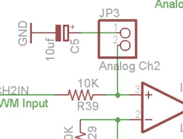
My thought is something like this picture I threw together. I would then only have to add an ethernet jack to my current Pi and then just have a second small box fed by the ethernet jack and house the converter. Then a TRS jack for how every many lights I would want it to control. Would this work, is this wiring correct for what I need? Obviously this only shows 1 light setup but I could expand for however many lights I would want to control. I don't see why it wouldn't work but want to be sure. I tried emailing Robo-tank and sending a message on here and haven't gotten a response.
Couple questions:
1) From what I've read other places I should be fine using ethernet cable for this purpose?
2) The Robo-tank board has a spot for Ground and "Controller ground"... Inside my Pi I have common grounds, can I just run one ground and jumper it to both spots on the robot-tank board
3) Any other opinions?


")