Some PCB design ideas for DIY LDD-L driver based builds

theatrus

Valuable Member
View Badges
Joined
Mar 26, 2016
Messages
1,966
Reaction score
3,360
Location
Sacramento, CA area
Rating - 0%
0   0   0
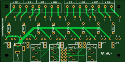
EZ-8 board in progress, this is the one I think I'll end up using the most, as most builds that I end up doing are either six or eight channels, for simple fishroom/growout setups. Not entirely happy with the power trace arrangement from the DC jack yet. Going to incorporate a simple jumpering scheme for the last two or four channels so that the fourth input can be left off as needed, probably in the same manner as the EZ Nano. One of these boards with a simple laptop (or other 18~30 volt) power brick, a handful of Luxeon Sunplus series LEDs, and a few sections of aluminum C-channel as heatsink would be a very economical way to outfit a small fishroom rack :)

EZ8_multi.png


EZ8_top.png


If you can't tell I like to post frequent updates while working, it keeps me motivated, breaks up the work, and helps pass the time :)

As always, suggestions are welcome.

Looks good - maybe add silk to number the channels on the output block? Easy to miscount. Also adding a little vertical line may help split each pair up visually.
 
OP
OP
Lingwendil

Lingwendil

Well-Known Member
View Badges
Joined
Jul 23, 2012
Messages
529
Reaction score
444
Location
Antioch, California
Rating - 0%
0   0   0
EZ Nano and EZ8 now feature solder bridge functionality so that solder blob jumpers can be fitted (or 0R 0805 SMD resistors if you're anal) to jumper the boards for 2 (nano) or 4/6 (on the 8) channels, respectively.
EZ8_multi29.png
LDDEZmulti29.png
 
OP
OP
Lingwendil

Lingwendil

Well-Known Member
View Badges
Joined
Jul 23, 2012
Messages
529
Reaction score
444
Location
Antioch, California
Rating - 0%
0   0   0
In fact, the more I think about it, maybe doing the 16UP with only the onboard PCA and I2S header, rather than individual channels may actually make a good bit of sense. it would actually make the layout easier, too. I'll still do the regular 16 with the header for input, but maybe make it have a single row of headers? Hmm.
 
OP
OP
Lingwendil

Lingwendil

Well-Known Member
View Badges
Joined
Jul 23, 2012
Messages
529
Reaction score
444
Location
Antioch, California
Rating - 0%
0   0   0
I'm almost happy with it, I swear :)

Added some silkscreen details, added the option for 0805 SMD pulldown resistors, and relocated the resistors under the drivers to save space, which made room for the jumpers to go next to each driver. I like this layout so much that I think I'll transfer it over to the larger PRO boards.

nanopro30.png
 
OP
OP
Lingwendil

Lingwendil

Well-Known Member
View Badges
Joined
Jul 23, 2012
Messages
529
Reaction score
444
Location
Antioch, California
Rating - 0%
0   0   0
Ok, now I'm happy with the Nano and 8UP pro, looks nice and tidy, and optimized the jumper traces. Each channel can be jumpered on/off, adjacent channels can be connected in parallel, and SMD resistors can be used. I like it.

8up-pro30.png


nanopro30.png
 
OP
OP
Lingwendil

Lingwendil

Well-Known Member
View Badges
Joined
Jul 23, 2012
Messages
529
Reaction score
444
Location
Antioch, California
Rating - 0%
0   0   0
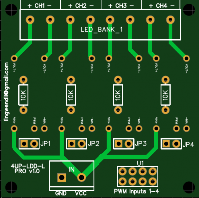
EZ Nano now modified for under-driver resistor layout, with added jumpers for enabling each channel. Also- I've changed my mind on solder-blob/SMD resistor jumper, and converted over to traditional pin-header style jumpers for the channel parallel feature. Feels a bit more polished :)

Next up will be the EZ8 board modifications.

EZNanomulti30.png
 
OP
OP
Lingwendil

Lingwendil

Well-Known Member
View Badges
Joined
Jul 23, 2012
Messages
529
Reaction score
444
Location
Antioch, California
Rating - 0%
0   0   0
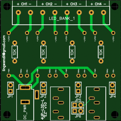
EZ8 board now features jumpers for on/off, as well as jumper block for parallel (4 or 6) channel operation. The 16 channel board is on the back burner for now, as I'm not sure exactly how I want to go for it. I'm not sure if I want to add all the on/off jumpers or not, or if I want to leave it with a header for input or include the PCA9685 chip onboard or not. As it sit now it would be a perfectly usable board, but may make the most sense with the PCA chip included.

EZ8multi31.png
 
OP
OP
Lingwendil

Lingwendil

Well-Known Member
View Badges
Joined
Jul 23, 2012
Messages
529
Reaction score
444
Location
Antioch, California
Rating - 0%
0   0   0
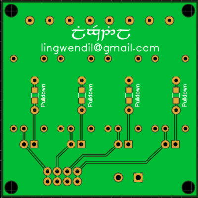
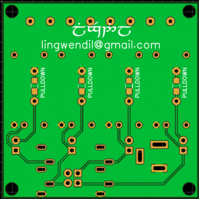
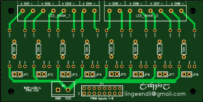
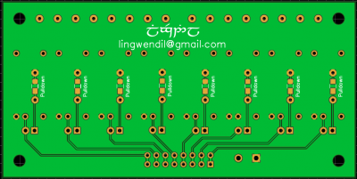
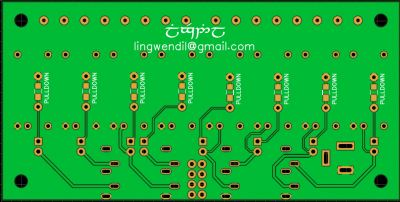
Alright, got the boards to a mostly final state for the 4 and 8 channel versions-

Nano Pro-
nanopro31top.png nanopro31bottom.png

Nano EZ-

EZNanotop31.png EZNanobottom31.png

8Up Pro-

8up-pro31top.png 8up-pro31bottom.png

8Up EZ-

EZ8top31.png EZ8bottom31.png

So far this has been a very enjoyable (and challenging!) project, and I'm very pleased with the boards so far. We have standard functionality across all four, with similar layout and schemes to make them easy to understand as well as making upgrades easy when moving from one to the next. Small too! The nano versions are 50mm (2") square, and the 8Up boards are 50x100mm (2x4") for nice compact builds.

Now we just need a cool logo or symbol of some sort to silkscreen onto them :)
 

theatrus

Valuable Member
View Badges
Joined
Mar 26, 2016
Messages
1,966
Reaction score
3,360
Location
Sacramento, CA area
Rating - 0%
0   0   0
Alright, got the boards to a mostly final state for the 4 and 8 channel versions-

Nano Pro-
nanopro31top.png nanopro31bottom.png

Nano EZ-

EZNanotop31.png EZNanobottom31.png

8Up Pro-

8up-pro31top.png 8up-pro31bottom.png

8Up EZ-

EZ8top31.png EZ8bottom31.png

So far this has been a very enjoyable (and challenging!) project, and I'm very pleased with the boards so far. We have standard functionality across all four, with similar layout and schemes to make them easy to understand as well as making upgrades easy when moving from one to the next. Small too! The nano versions are 50mm (2") square, and the 8Up boards are 50x100mm (2x4") for nice compact builds.

Now we just need a cool logo or symbol of some sort to silkscreen onto them :)

Looking nice. Is there enough clearance from the holes for average sized screws? Not keeping enough keepout bites me from time to time.

What PCB software are you using?
 
OP
OP
Lingwendil

Lingwendil

Well-Known Member
View Badges
Joined
Jul 23, 2012
Messages
529
Reaction score
444
Location
Antioch, California
Rating - 0%
0   0   0
I think the only issue will be on the Nano boards, the clearance looks really tight near the LED output connector, I think it may be fine with socket-cap machine screws, but I want to print out a 1:1 size copy on paper for mockup to see. Worst that will happen is that I'll change to a 2.54mm spacing connector for the Nano boards, although I would ideally keep it to the regular screw terminals that are easy to find.

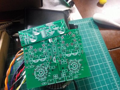
PCB software is the lovely and noob-friendly https://easyeda.com/ as it is easy to use, and requires no download. 99% of my PCB work is done during downtime at work, since I rarely have time at home. Very handy. I first found out about it from a guy on DIYaudio, and found it much easier to use than many of the other (often expensive) programs. I've done a few PCB designs for vacuum tube amplifier projects with it first, and have been very pleased-

IMG_20180613_204406.jpg
 

reeph

New Member
View Badges
Joined
Jan 31, 2019
Messages
16
Reaction score
31
Location
Austria
Rating - 0%
0   0   0
Hi :)

I made an account just to answer to your thread. First of all, really nice work!
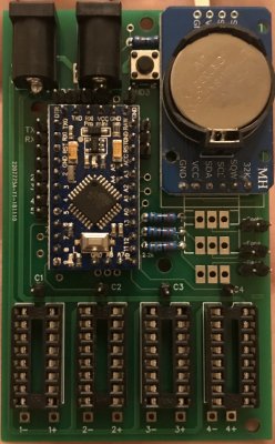
I have made something similar for my DIY LED build and therefore I wanted to show it to you :)

IMG_6066 2.jpg

I made this PCB also with easyeda! Super easy to use and really fun!
My PCB has place for 4 Meanwell LDD drivers, a Real Time Clock, 3 transistors to switch on the fan, or a cooling fan or so, one button and one Arduino Pro Mini.

As you can see, I have used sockets for my drivers. If one driver would fail one time, I could easily replace it with a new one.
Basically, I wanted to show you, that you could use sockets if you want on your PCB. But if you do not bother soldering them out when they break, then you do not need such a socket :)

Cheers!
 
OP
OP
Lingwendil

Lingwendil

Well-Known Member
View Badges
Joined
Jul 23, 2012
Messages
529
Reaction score
444
Location
Antioch, California
Rating - 0%
0   0   0
Cute little board! What code do you run?

EasyEDA is really fun, it's actually more enjoyment than I've had doing electronics in a while. Easy to make small incremental changes as you go.


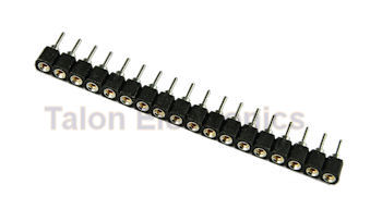
For my drivers, I was going to give the option of sockets to the builder. On the LDD-H boards I've used I broke apart the SIP machined headers, and used them at each pin, they work nicely-

SIP1X18.jpg
 

reeph

New Member
View Badges
Joined
Jan 31, 2019
Messages
16
Reaction score
31
Location
Austria
Rating - 0%
0   0   0
I run my own written code on it, for dimming the lights on in the morning and off in the evening, and other little stuff :)

Oh, I also have some of these pins at home. I will try them, maybe I will change my PCB layout for the pins :)
 

Macca_75

Active Member
View Badges
Joined
Jan 31, 2019
Messages
369
Reaction score
166
Rating - 0%
0   0   0
@Lingwendil - is there any chance f changing the PWM inputs to a RJ45 (1 wire for ground and the rest for PWM signal) and also adding another RJ45 (out) so the boards can be daisy chained?
 
OP
OP
Lingwendil

Lingwendil

Well-Known Member
View Badges
Joined
Jul 23, 2012
Messages
529
Reaction score
444
Location
Antioch, California
Rating - 0%
0   0   0
It could be done, yes, but I think I would rather do so with a connector that plugs over the pin headers, unless there is sufficient interest to warrant it. After these are finalized I can look into doing a version for it.


Also, as an astute member mentioned via PM, there are a few missing traces on the bottom of the 8Up boards, those have been fixed, somehow they were tied to the GND net and sunk into the ground pour:confused:
 

Kampo

Active Member
View Badges
Joined
Dec 19, 2017
Messages
349
Reaction score
327
Location
South West Michigan
Rating - 0%
0   0   0
@Lingwendil - is there any chance f changing the PWM inputs to a RJ45 (1 wire for ground and the rest for PWM signal) and also adding another RJ45 (out) so the boards can be daisy chained?
you could always get a RJ45 breakout like this:
upload_2019-2-1_9-12-36.jpeg

could slot right into this you would just need to jumper channel 8 into whatever channel you want it to mirror:
8up-pro31top-png.963373
 

Just grow it: Have you ever added CO2 to your reef tank?

  • I currently use a CO2 with my reef tank.

    Votes: 8 6.3%
  • I don’t currently use CO2 with my reef tank, but I have in the past.

    Votes: 5 3.9%
  • I have never used CO2 with my reef tank, but I plan to in the future.

    Votes: 6 4.7%
  • I have never used CO2 with my reef tank and have no plans to in the future.

    Votes: 103 80.5%
  • Other.

    Votes: 6 4.7%
Back
Top