really need to look into this. would love to take one of these board designs as a base then add a bit to the board to make a spot to mount a ESP32 board. been messing arround with one this week. I'm really surprised that more haven't jumped on these boards for Light controllers. the person who created SSLAC16 for esp8266 ported his code + improved it greatly. and its simple and not pretty but does the job (I feel this is the russian way lol) only needs a ESP32 board + RTC does 16 channels of control and can be configured for lights/dosing/fans/relay. got one running on one of my planted tanks to see what issues it has but so far so good. got a few more boards on the way from china to tinker with on my other lights.

Navigation
Install the app
How to install the app on iOS
Follow along with the video below to see how to install our site as a web app on your home screen.
Note: This feature may not be available in some browsers.
More options
You are using an out of date browser. It may not display this or other websites correctly.
You should upgrade or use an alternative browser.
You should upgrade or use an alternative browser.
Some PCB design ideas for DIY LDD-L driver based builds
- Thread starter Lingwendil
- Start date
- Tagged users None


OP
OP
Over on ultimate reef they're doing a version of their 16 channel with an ESP8266 and the PCA chip and 6 onboard LDD-L drivers, I may end up doing something similar. For now I'm happy with the version I run, but it's not the most user friendly interface, once the wifi option is there for config it should be a nice improvement in functionality.
I tried that SSLAC project a while back, but couldn't ever get it to upload properly, so I'll have to revisit it. An 8 channel with onboard controller, and a pin header for full channel control expansion would be really nice")
I tried that SSLAC project a while back, but couldn't ever get it to upload properly, so I'll have to revisit it. An 8 channel with onboard controller, and a pin header for full channel control expansion would be really nice
Over on ultimate reef they're doing a version of their 16 channel with an ESP8266 and the PCA chip and 6 onboard LDD-L drivers, I may end up doing something similar. For now I'm happy with the version I run, but it's not the most user friendly interface, once the wifi option is there for config it should be a nice improvement in functionality.
I tried that SSLAC project a while back, but couldn't ever get it to upload properly, so I'll have to revisit it. An 8 channel with onboard controller, and a pin header for full channel control expansion would be really nice
Took me a bit to figure it out but it was a driver issue. Once I figured that out his flashme.bat worked perfectly. I have been following the project you speak of. might look at it when the wifi stuff is done. this is the new "SMAC" project for the esp32 https://github.com/bbasil2012/SSLAC-ESP32

Hello friends!this is the new "SMAC" project for the esp32 https://github.com/bbasil2012/SSLAC-ESP32
I am the author of the project SMAC16
I am very glad that you use it.
I'm here and ready to help you with it!
Awesome I might hit you up with some questions when I build a more complex one. Once I figured out the flashing it all worked as it should.Hello friends!
I am the author of the project SMAC16
I am very glad that you use it.
I'm here and ready to help you with it!

I think it would be wise to make two new threads about smac16:
1.software - firmware, flashing, hits&tricks, hacks.
2.hardware - wiring, drivers, relays, fans, sensors, etc.
agree make one up then
your the creator one thread is prolly sufficent I think. good friendly place for your english speaking followers of the project here. I'd link back to the reefcentral.ru thread as well though, used google translate to figure things out. wiring diagrams for all the supported drivers/sensors/relays/fans would be a nice thing as well. I can prolly figure it out myself since this is the 4th devboard i've messed with but a newby would struggle finding where to start.
OP
OP
I think it would be wise to make two new threads about smac16:
1.software - firmware, flashing, hits&tricks, hacks.
2.hardware - wiring, drivers, relays, fans, sensors, etc.
Start a thread! I'm sure it would be a very popular project over here! I've got some questions I'll reserve until a thread is up for it, so as to not derail this one.
OP
OP
Ok, here we go! here are the (tentative) final versions of the 4 and 8 channel boards!


Still feels a bit unfinished without a logo or little graphic of some sort. I'm trying to figure out what to throw on there, maybe a little dead fish, or something else a bit goofy?


Anybody want to replace that orca in the bowl with the fish for me? I'll send you a couple of the first boards once I order them
Or- even better- lets find a Tang to put in that bowl!!!
Maybe a generic reef looking fish (butterfly?) like this one?

Any other suggestions for a small graphic would be appreciated. The above came from Openclipart.org, and are royalty-free, and open for unlimited use, btw. Handy resource.
Still feels a bit unfinished without a logo or little graphic of some sort. I'm trying to figure out what to throw on there, maybe a little dead fish, or something else a bit goofy?
Anybody want to replace that orca in the bowl with the fish for me? I'll send you a couple of the first boards once I order them
Or- even better- lets find a Tang to put in that bowl!!!
Maybe a generic reef looking fish (butterfly?) like this one?
Any other suggestions for a small graphic would be appreciated. The above came from Openclipart.org, and are royalty-free, and open for unlimited use, btw. Handy resource.
Last edited:

- Joined
- Jan 31, 2019
- Messages
- 369
- Reaction score
- 166
Ok, here we go! here are the (tentative) final versions of the 4 and 8 channel boards!
And from a purley selfish and unrelated question.
Any chance of getting a second connector for the PWM signal so i could daisy chain boards?
And what are the dimensions of this bad boy. Could I be so lucky......
(oh - and does it support the LDD-H drivers)???
OP
OP
These versions of the "PRO" boards do in fact featured parallel headers for PWM, so if you aren't running jumpers to parallel the channels they can easily be daisy chained. The eight channel boards are 100mm wide, and I will reduce this to ~99.5mm for compatibility with the Maker's heatsink upper PCB slot, after testing fit with the one I have here. In addition to files for single boards, I'll be panelizing the designs so that four PCBs of the nano will fit a single 100mmX100m board (4x10, so a typical 10 board order will make 40x nano boards!) And so that two of the 8up (2x10, so 20X 8up boards) will fit a single board. This will give the option to buy a bunch or a few, depending on your needs and the PCB house pricing table. They should be rather cheap at most places.
Keep in mind that the LDD-L is limited to 700mA and 32 volts out with these boards, due to the driver itself.
As for the LDD-H, unfortunately these boards will not be compatible with them... They are physically much larger-

I do have plans for a set of LDD-H boards, but due to the larger size I think the most I can fit on a 50x100 board is five or six if the intention is to fit in the Maker's heatsink.
If you need the RJ45 connectors I can work up a version for you, I just need suggestions on ones to feature on the board, based off of what is available in your area from the usual distributors.
Keep in mind that the LDD-L is limited to 700mA and 32 volts out with these boards, due to the driver itself.
As for the LDD-H, unfortunately these boards will not be compatible with them... They are physically much larger-
I do have plans for a set of LDD-H boards, but due to the larger size I think the most I can fit on a 50x100 board is five or six if the intention is to fit in the Maker's heatsink.
If you need the RJ45 connectors I can work up a version for you, I just need suggestions on ones to feature on the board, based off of what is available in your area from the usual distributors.

OP
OP
So, the most I can fit of the LDD-H on a 100mmX50mm board is four, but I can easily do six (or eight) on a 100mm square board, with room for output and input headers easily. I think I'll start with the eight, and then carve it down to four. Any special requests here?
Also, should I add a power LED to the LDD-L boards? Might be useful to tell the board itself is hot for troubleshooting...
Also, should I add a power LED to the LDD-L boards? Might be useful to tell the board itself is hot for troubleshooting...
Any special requests here?
Also, should I add a power LED to the LDD-L boards? Might be useful to tell the board itself is hot for troubleshooting...
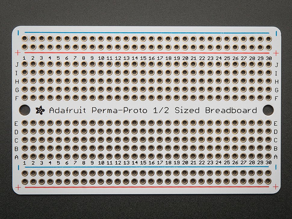
an idea I had. I was looking at what it would take to design my own with a header setup for a esp32, and I thought I wounder how helpful it would be to add a "protoboard" section attached to it. would let someone drop in a pizero/esp32/bluefish mini and then just use jumper wires to get them to the propper header locations. could make building a neat and clean controller a bit easier.
something like this as part of the board
OP
OP
I think we can do something like that
Maybe on one of the eight channel LDD-L boards, or on a four channel LDD-H board? That way we could have half of a 100mm square PCB be dedicated to prototyping and one-offs. Hmmm. It would make it easy for Bluefish, ESP8266 or ESP32 solutions to have room to add the level-shifter circuitry for converting the PWM to a usable level for the L drivers, and also have room for custom onboard power supply step converter modules.
Maybe on one of the eight channel LDD-L boards, or on a four channel LDD-H board? That way we could have half of a 100mm square PCB be dedicated to prototyping and one-offs. Hmmm. It would make it easy for Bluefish, ESP8266 or ESP32 solutions to have room to add the level-shifter circuitry for converting the PWM to a usable level for the L drivers, and also have room for custom onboard power supply step converter modules.

OP
OP
LDD-H board preliminary draft, still need to work in the PWM traces and jumpering for on/off, as well as daisy chaining/parallel channels. Maybe an additional 2x8 header for that?

OP
OP
Wasn't happy with the power trace, so I rerouted it, and relocated the pulldown resistors. Routed the PWM traces, and now I'll place 2x2 jumper blocks under the bottom four drivers, so that channels 1/2, 3/4, etc will have jumpers adjacent to eachother for easy on/off troubleshooting. I also added an additional pair of power connections, for easy daisy-chaining of power to additional boards.

OP
OP
Whew. I think it's pretty close to done. I'm going to add a couple additional power traces to support full current operation, otherwise I think it's all there.


Last edited:
OP
OP
And there we go, individual power traces to each driver are 1.5mm, big traces are 3.5mm. Should be plenty of headroom to run 1.5A drivers per slot if needed, so long as the power connector and power supply are up to the task

OP
OP
And the muti layer view of above after a few more tweaks-

Similar threads
- Replies
- 63
- Views
- 1,850
- Replies
- 8
- Views
- 396