Some PCB design ideas for DIY LDD-L driver based builds

OP
OP
Lingwendil

Lingwendil

Well-Known Member
View Badges
Joined
Jul 23, 2012
Messages
529
Reaction score
444
Location
Antioch, California
Rating - 0%
0   0   0
Oh dang!

PCBs came in, that box was surprisingly heavy :)
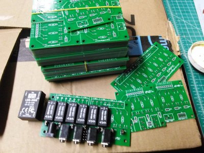
IMG_20190218_182954.jpg

So far, the cheap jack I bought to try for fit is a tad loose until soldered, but otherwise fits perfectly once you solder it down. Because this one was cheap enough, and the fact that Arrow offers free shipping, one can order the power jack and PWM jacks along with other accessories from them to save money. I'm waiting on the cheap screw terminals I ordered to come in on the slow boat, so I can't finish up any of the nano boards yet, as I don't want to spend $5 each on them :)
 

Macca_75

Active Member
View Badges
Joined
Jan 31, 2019
Messages
369
Reaction score
166
Rating - 0%
0   0   0
Top pins are connected to the pins directly below them, and all are PWM. No ground pins are currently implemented on the input headers, as the assumption that the controller will be sharing the PSU ground is in place. I can add a jumper to the last two channels so that those two input pins can be grounded if that helps you? That way you can choose to ground pin 7, 8 if needed, and then you need to install either an SCW in those spots, or run a jumper from whichever other channel you wish to have that LDD share its PWM from.
Thanks - based on the testing I am doing at the moment (LED are run off 1 PSU in total isolation) I am trying to control with a Profilux. Converting 1-10V on Profilux to PWM (using Arduino) so I would need a separate GND to pass along.

So yes please to the addition pair of pins, connected to ground.
 

Macca_75

Active Member
View Badges
Joined
Jan 31, 2019
Messages
369
Reaction score
166
Rating - 0%
0   0   0
Nice
Oh dang!

PCBs came in, that box was surprisingly heavy :)

IMG_20190218_182954.jpg

So far, the cheap jack I bought to try for fit is a tad loose until soldered, but otherwise fits perfectly once you solder it down. Because this one was cheap enough, and the fact that Arrow offers free shipping, one can order the power jack and PWM jacks along with other accessories from them to save money. I'm waiting on the cheap screw terminals I ordered to come in on the slow boat, so I can't finish up any of the nano boards yet, as I don't want to spend $5 each on them :)
- are you soldering sockets for the Drivers to plug into (making it easier to change Amps down the track)?
 
OP
OP
Lingwendil

Lingwendil

Well-Known Member
View Badges
Joined
Jul 23, 2012
Messages
529
Reaction score
444
Location
Antioch, California
Rating - 0%
0   0   0
Yup. I'm going to use individual pin machined IC sockets (the kind that come in a long strip that you cut off how much you need) My usual way of getting color where I want it is mixing and matching drivers to get it as close as I can, and then relying on PWM to fine tune it or adjust color temp throughout time of day. Sockets are a must.
 
OP
OP
Lingwendil

Lingwendil

Well-Known Member
View Badges
Joined
Jul 23, 2012
Messages
529
Reaction score
444
Location
Antioch, California
Rating - 0%
0   0   0
Minor issue-

It appears that the 8position output terminals chosen have the holes in the eight channel PCBs too small to allow the terminals to be installed into the board! None of the screw terminals that I have tried will fit the boards, and I'm not having any luck with finding any listed for sale with smaller pins. As it is now the boards will work just fine, but will require the wiring to be soldered directly to the PCB, rather than being attached via screw terminals. Boards are otherwise perfect, I populated a Nano Pro completely without issue, and plan to swap it into my freshwater nano tonight.

So, unless anybody has a lead on 5.08mm screw terminals with smaller pins, I think I need to revise the boards. I think I might just switch over to the same 2.54mm spaced miniature screw terminals for the eight channel boards as well, or simply enlarge the pin holes in the PCB files. Either solution is very easy, but I sort of want to retain the full-size screw terminals in order to take advantage of the cheap 50x and 100x packs available as they are pretty darn affordable.

Hmmmm.


I already see places for improvement- I think the addition of a footprint for a 12 volt regulator (for controllers, fans, etc) to the 8up boards would be a nice addition, as well as a couple extra header pins for power and ground at the PWM headers. As it is now the Pro boards assume the controller shares the same PSU, so a ground pin is not provided. It would be very easy to add a couple pins on either side for versatility. Not sure if I want to mess with a regulator module for the 4up boards, but I think one could fit. Hmmm.

I'll mess with the LDD-H boards a bit more too here pretty soon :)


Anybody interested in buying some of the current LDD-L PCBs let me know, I will be selling the current versions of the nano boards in sets of four, and 8up boards in sets of two, $7 shipped within the US. A set of eight nano, or four 8ups $10 shipped, mix and match available! PM if interested. Both the "PRO" (header-input) and "EZ" (audio/barrel jack) version of each are available. Blowing them out cheap to get them out there, and plan to update the design later on as time allows.
 
OP
OP
Lingwendil

Lingwendil

Well-Known Member
View Badges
Joined
Jul 23, 2012
Messages
529
Reaction score
444
Location
Antioch, California
Rating - 0%
0   0   0
I've attached the current versions of the boards, with the fixed hole sizes (referring to the last post as to the issue) for the output terminals, these are absolutely ready to use, and my recommendation on a PCB house for small orders is JLCPCB. You can panelise these when ordering, so that 4x nano or 2x pro boards will make up a single 100x100mm board, getting you 40 or 20 each. You can also order as-is to get a set of ten.

They should be self explanatory, but EZ= onboard jacks for input/power, and PRO= headers and screw terminals for input/power.
 

Attachments

  • LDDLEZPRONANO8_V1.zip
    584.7 KB · Views: 234
OP
OP
Lingwendil

Lingwendil

Well-Known Member
View Badges
Joined
Jul 23, 2012
Messages
529
Reaction score
444
Location
Antioch, California
Rating - 0%
0   0   0
Yeah, I'm going to give them a last once-over and then I'll revisit how to arrange the input headers to get a reasonable ground pin arrangement for you. I think easiest is a pair of ground pins on either end, and then you can add jumpers as needed to double up the last channel or two. I've been taking a break to keep from getting burnt on on PCB design before I mess with it much more. I'll revisit the H boards in a day or two.
 
OP
OP
Lingwendil

Lingwendil

Well-Known Member
View Badges
Joined
Jul 23, 2012
Messages
529
Reaction score
444
Location
Antioch, California
Rating - 0%
0   0   0
Here you go, I replaced the input header with a 2x10, and both ends are ground pins, so that you can plug in the input offset to whichever side is more convenient, and jumper channels in parallel as needed. For example, if you treat pin1 as ground, you would jumper channels 7,8 in parallel in order to run them off of the same PWM, or run channel 8 as an SCW module for seven channels of control... Think this will work for you?

POBsB3SNr84.png
 
Last edited:

Macca_75

Active Member
View Badges
Joined
Jan 31, 2019
Messages
369
Reaction score
166
Rating - 0%
0   0   0
From my limited technical knowledge it looks good.

1) What are J1/J2/J3, etc for?
2) How do I order/print these boards? I am in Aus so happy to either organise myself or purchase from you.
3) Just confirming the dimension slot into MakersLED heat sink?

Thanks again in advance.
 
OP
OP
Lingwendil

Lingwendil

Well-Known Member
View Badges
Joined
Jul 23, 2012
Messages
529
Reaction score
444
Location
Antioch, California
Rating - 0%
0   0   0
The j1-j8 jumpers are for enabling the pulldown resistors, useful for troubleshooting.

To order, you simply upload the zipped design files, and choose the shipping options you want, I like JLCPCB. Let me look over everything more tomorrow and I'll get a "version 1.0" release zipped and ready. I'll start a dummy order so I can lay out some simple instructions for you. Should be easy peasy and around $16USD shipping at most I think...

The boards will slot into the maker's sink :)
 
OP
OP
Lingwendil

Lingwendil

Well-Known Member
View Badges
Joined
Jul 23, 2012
Messages
529
Reaction score
444
Location
Antioch, California
Rating - 0%
0   0   0
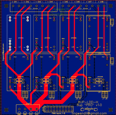
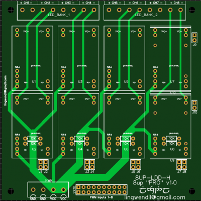
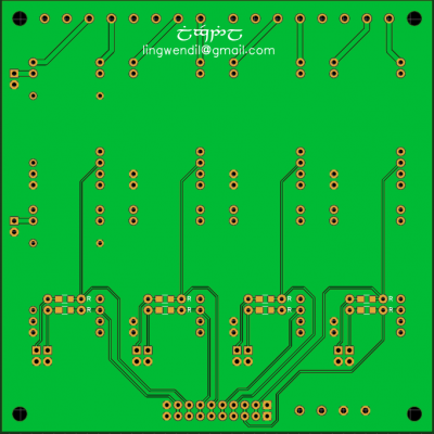
Alright- current state of the LDD-H 8up boards-

LDDHPROmulti.png
LDDHPROtop.png
LDDHPRObottom.png


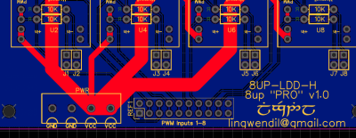
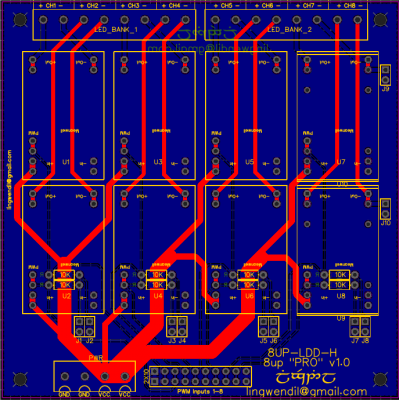
As stated above, this can be used with an SCW in either position 7 or 8, and features jumpers j1-j8 for the pulldown resistors, if not using pulldowns they need not be populated, but are a handy test feature and are recommended. The outputs will route to the same output terminals as the LEDs to make things simple, unless another connector on the opposite side of the board is desired... Which would not be too tricky to add. Let me look things over a bit more (and maybe tweak a few things) but it looks pretty close to done, in my opinion.
 
OP
OP
Lingwendil

Lingwendil

Well-Known Member
View Badges
Joined
Jul 23, 2012
Messages
529
Reaction score
444
Location
Antioch, California
Rating - 0%
0   0   0
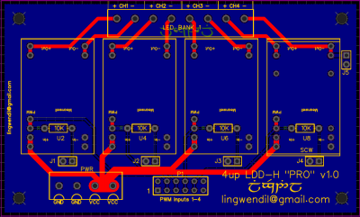
Finally had enough downtime (at work) with a computer so I could go back to this. I think the meat of the LDD-H 4up and 8up boards are done. I'm thinking of adding an additional 2P screw connection on the right bottom corner for the output of the SCW blocks, but I'm not sure it would be useful enough? As it sits now one could easily use the output from the LED side but maybe having an additional set could streamline things for some uses? Looking forward to thoughts on this.

4uppro04252019.png
8uppro04252019.png
 

Macca_75

Active Member
View Badges
Joined
Jan 31, 2019
Messages
369
Reaction score
166
Rating - 0%
0   0   0
This is beyond my knowledge. Why would you want the additional terminals? Is it to grab power or something?
 

kegler

New Member
View Badges
Joined
Apr 25, 2019
Messages
22
Reaction score
3
Rating - 0%
0   0   0
Finally had enough downtime (at work) with a computer so I could go back to this. I think the meat of the LDD-H 4up and 8up boards are done. I'm thinking of adding an additional 2P screw connection on the right bottom corner for the output of the SCW blocks, but I'm not sure it would be useful enough? As it sits now one could easily use the output from the LED side but maybe having an additional set could streamline things for some uses? Looking forward to thoughts on this.

This (the SCW capability) will work well for me for my application, as I will be using an Arduino with my setup down the road.

However this will only work with the SCW05 and SCW08 converters only. SCW12 converters have remote control power up/down on pin 1 . This pin/feature is not present on the on the 05 & 08 converters. Since this pin is tied to the ground plane on the board for LDD-H for use, the SCW12 will always remain in a powered down state. Won't hurt anything, the SCW12 just won't power-up. To work around it you would have to isolate that pin and ground it for LDD-H use, or make that pin accessible for SCW12 R/C use. I just don't think it's worth the trouble at this time. Maybe next version. If someone does need to use a SCW12, clip off (or don't connect) pin 1 from the converter, which will result in the converter always being in a powered up state like the 05 & 08 converters.

A note should be made concerning J5 on the 4up and J9 & J10 on the 8up: Do not use a LDD-H in the associated slot WITHOUT removing the jumper. The LDD-H datasheet states you should NOT connect -vIn to -vOut , which is what that jumper does. It is safe for the SCW converter, but not the LDD-H. Mean Well does not say what will happen if you do, just don't do it.

As for the 2P screw connection for use with the SCW, it would be nice to have but not absolutely necessary IMO.

Looks good to me otherwise.

Jim
 
OP
OP
Lingwendil

Lingwendil

Well-Known Member
View Badges
Joined
Jul 23, 2012
Messages
529
Reaction score
444
Location
Antioch, California
Rating - 0%
0   0   0
Thanks for the input!

I just noticed that JLCPCB is allowing other colors on the cheap board deals now, what color should we do on the LDD-H boards, and future runs of the LDD-L? I'm thinking either Blue or White would be a nice option, both look a bit nicer than green- and I'm partial to the White... I may switch to either on the next run of tube project PCBs too.
 
Back
Top