Some PCB design ideas for DIY LDD-L driver based builds

Macca_75

Active Member
View Badges
Joined
Jan 31, 2019
Messages
369
Reaction score
166
Rating - 0%
0   0   0
And the muti layer view of above after a few more tweaks-

LDD_H8multiSEMIFINAL.png
Love where this ended up (or is it finished
?)
 
OP
OP
Lingwendil

Lingwendil

Well-Known Member
View Badges
Joined
Jul 23, 2012
Messages
529
Reaction score
444
Location
Antioch, California
Rating - 0%
0   0   0
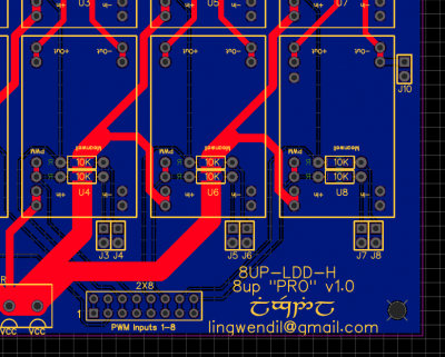
It's close to done. I've added a couple jumpers and pin positions to allow meanwell SCW converters in spots 7/8 as an option. Now I'm just mulling over if there's anything else I should add or change.

Will this board work for you? Any particular changes that you would want? The board is 99.5mm square currently, and should work in the maker's sink.
 
OP
OP
Lingwendil

Lingwendil

Well-Known Member
View Badges
Joined
Jul 23, 2012
Messages
529
Reaction score
444
Location
Antioch, California
Rating - 0%
0   0   0
Just checked my maker's sink, even the 100mm PCBs I have on hand for other projects slip right in with about a millimeter of wiggle room, so I think I'll stick with 100mm on these, that way they aren't too loose.
 

Macca_75

Active Member
View Badges
Joined
Jan 31, 2019
Messages
369
Reaction score
166
Rating - 0%
0   0   0
It's close to done. I've added a couple jumpers and pin positions to allow meanwell SCW converters in spots 7/8 as an option. Now I'm just mulling over if there's anything else I should add or change.

Will this board work for you? Any particular changes that you would want? The board is 99.5mm square currently, and should work in the maker's sink.
As far as I can tell it's perfect. I currently have the DC-DC chip - I think it is used to power the BF mini?

Will the BF mini plug straight on (if that's what someone wanted to do)? I am guessing No as you would need to loose 2 pins/channels from the connector for power and ground...
 
OP
OP
Lingwendil

Lingwendil

Well-Known Member
View Badges
Joined
Jul 23, 2012
Messages
529
Reaction score
444
Location
Antioch, California
Rating - 0%
0   0   0
As it is now it's not a direct plug in, I'll have to check the pinout on the bluefish to see what would change there to be a direct plug. I don't have one on hand. Maybe I'll add a pigtail or header for power specifically, that way it can be a self contained unit, with two parallel driver on channel 6/7 controlled off the sixth channel, and the 12 or 5 volt SCW on the eighth channel to power the bluefish.

You have six channels of control planned, right? Do you know what the pinout you will use will be? If sharing ground between the controller and power you can use CAT5 for all eight channels of control if desired, it would be handy. Not sure if that helps you.

I can add a couple more pins for ground on either side of the PWM header so that it's a bit more versatile, if that helps. Then you can scoot the Ethernet plug over to either side to do it all direct... Does that make sense? I just want to make sure this will work for as many folks as possible, especially you :)
 

Macca_75

Active Member
View Badges
Joined
Jan 31, 2019
Messages
369
Reaction score
166
Rating - 0%
0   0   0
Personally it would work for me. I am passing Ground and 6 signals so a ground would be good.

You could use 6 LDD-H and a DC-DC to pass voltage to BF mini (along with ground) so that would be 8 pins capable of driving 6 channels and a BF mini.

I have the pin out if you need it.
 
OP
OP
Lingwendil

Lingwendil

Well-Known Member
View Badges
Joined
Jul 23, 2012
Messages
529
Reaction score
444
Location
Antioch, California
Rating - 0%
0   0   0
If If you have the pinout that would be great, I'm having a hard time finding it for some reason. I do want to draw up a six channel version with a header to plug it right in.

For your application, If you put an SCW in either position 7 or 8, and install a wire link instead of the resistance for that pulldown that will ground the pin for you nicely, without any other changes to the board. Do it in the seventh driver slot, and run 6/7 in parallel or leave position 7 open. Easy peasy.

I'll mess with it more Monday, no good computer access until then. Once it's looking good to everyone I'll share the files, and order some boards well, the LDD-L boards, at least, I don't currently need an eight channel for the LDD-H, although a four would be nice and is next on the to-do list. I'm doing some pendants that need 44 volts at 300~600mA so could use a board there.
 
OP
OP
Lingwendil

Lingwendil

Well-Known Member
View Badges
Joined
Jul 23, 2012
Messages
529
Reaction score
444
Location
Antioch, California
Rating - 0%
0   0   0
PCBs are ordered!!!

The hype is real. I ordered a set of each of the 4up and 8up LDD-L boards. Shipping gets expensive quick, so. I'll split everything else off into another order soon, once I finish the LDD-H versions.

This order: 40x EZ nano, 40x nano pro, 20x EZ8, 20x 8up pro. Cost was the same to buy singles versus buying multiples (if it fits in 100mm square, it costs the same as a 100mm square :)) so I went whole hog on them. Shipping went up of course, but this still lets the boards be nice and affordable. I'll have some available (and will post the design files) once I have them in hand and tested.

If anyone is interested in testing the LDD-L boards, let me know. I'll hand out a few to those in the US (unless anyone knows reliable and cheap international shipping methods for small PCB sized items.

Currently "finished" (more or less, assuming boards test correctly)

LDD-L 4up pro
LDD-L 8up pro
LDD-L 4up "EZ"
LDD-L8up "EZ"

Currently in-progress designs-

LDD-H 8up pro (you've all seen this one)
LDD-H 4up pro (basically just a cut-in-half 8up board, but you know, correctly. Natural evolution)
LDD-H 6up "Blue Six" board (bluefish-specific board, hopefully for direct plug-in of the Bluefish Mini controller)

Maybe in the future-

LDD-L 6up "Blue Six Mini" (with onboard PWM level conversion, and Bluefish mini plug-in support)
LDD-H 4up "EZ" (onboard DC jack and TRS jacks for input, as in the LDD-L "EZ" versions)
LDD1000-1200L/LDB-L combo board (if you aren't familiar with the LDB, it's a buck-boost driver, same style as the H-series, just with the capability of supplying higher output voltage than input voltage- handy little driver) https://www.ledsupply.com/led-drivers/mean-well-ldb-l-series-cc-buck-boost-mode https://www.meanwell.com/webapp/product/search.aspx?prod=LDB-L&mws=967866571357E3D9

Back-burner designs-

LDD-L 16up board (I think stacking 8ups makes a bit more sense, I may revisit later)
 
OP
OP
Lingwendil

Lingwendil

Well-Known Member
View Badges
Joined
Jul 23, 2012
Messages
529
Reaction score
444
Location
Antioch, California
Rating - 0%
0   0   0
https://easyeda.com

It's web based and very user friendly, as well as free!!! Pretty easy to use once you get the hang of it. Best suggestion is just practice, and then delete it all, place the parts differently, and then start again. Take into account what would be the easiest layout to keep power and signal traces short, and go from there. It's pretty easy to do the basics, and then reach out for support from those with experience to optimize it. I find brainstorming/blogging types of threads as this very helpful for suggestions and overall feedback.

It's a very enjoyable way to pass time, as well.
 
OP
OP
Lingwendil

Lingwendil

Well-Known Member
View Badges
Joined
Jul 23, 2012
Messages
529
Reaction score
444
Location
Antioch, California
Rating - 0%
0   0   0
Just ordered an SCW-05C-12, the TRS jacks, a couple cheap DC jacks that may fit, and a sack of 250 SMD 10K resistors from Arrow, free shipping made it worth it for the SCW alone. I also included a couple of the 6-channel level shifters in the order as well, to play with a design for them to run the BlueFish directly into a set of LDD-L drivers. The LDD-L should be a good fit size wise for a powerful PCB for nano builds if we can incorporate the BlueFish directly into the design, with no external wiring, and the only thing next to play with is an onboard power regulator to run them both, I'm thinking the LM2596 since it is still doable by hand soldering techniques, since we will only likely be wrking with 36 volts on the L boards. This is tentatively being called the "Blue6" board :)
 
OP
OP
Lingwendil

Lingwendil

Well-Known Member
View Badges
Joined
Jul 23, 2012
Messages
529
Reaction score
444
Location
Antioch, California
Rating - 0%
0   0   0
@Macca_75

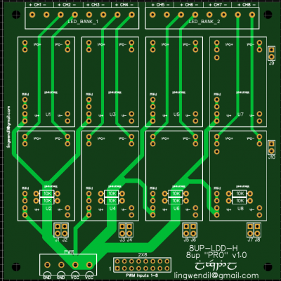
Here's the LDD-H 8up board as it sits now. You can run an SCW in either slot 7 or 8, and simply put a wire across the position for the corresponding resistor for that channel, this will ground that pin for you on the input header. THis will allow you to use a female header for input, and slot in the Ethernet breakout that was shown earlier in the thread. Will this work for you? If not I can figure out a creative jumper arrangement for you, but I think this will do what you want. As it is now, J9 and J10 will enable the SCW to output their voltage at the LED output header for that channel, so that it can be routed off as necessary to wherever it is needed, should you choose to do so.

snibbedysnabSCW0216.png

lddh80216top1.png
 
OP
OP
Lingwendil

Lingwendil

Well-Known Member
View Badges
Joined
Jul 23, 2012
Messages
529
Reaction score
444
Location
Antioch, California
Rating - 0%
0   0   0
Well, after some diffing, it looks like the typical maximum power consumption of the Bluefish Mini is around ~370mA, so a small SMPS block will work just fine. I'm looking at using this for the 5 volt supply to both the Bluefish and the level converter IC-

VX7805-500
https://www.digikey.com/short/p3wbd3

I think this will do just fine for us, as I would rather stick to simple modules, rather than more complicated onboard circuitry for this. A couple small capacitors onboard and we're done with this guy. Price is right, too :)
 
OP
OP
Lingwendil

Lingwendil

Well-Known Member
View Badges
Joined
Jul 23, 2012
Messages
529
Reaction score
444
Location
Antioch, California
Rating - 0%
0   0   0
Looking at the logistics of doing a bluefish mini all-in-one board, it looks like the only real tricky part is sourcing right-angle 2x7pin female header blocks, they seem almost nonexistent from the usual places. I found some on ebay, so they are out there. I'll likely put a female header onboard, and then have a right-angle header that plugs ito the bluefish, and then into the board. It sounds more complicated than it is, but it's what O2 did on his larger boards that featured bluefish support, and from the research I've done it makes the most sense. Only other reasonable option seems to be putting the bluefish offboard and using a ribbon cable, which I personally would rather avoid if possible.

Bluefish looks to be 3.5cmX6cm, so it looks like stripping the 8up board down to six, relocating driver no.6 to the bottom left of the board, and extending the board to ~70mmX100mm should give us plenty of room, with a 16TSSOP package for the level converter so it can be on either the bottom of the board or on top underneath the bluefish module. I know I was trying to avoid SMD for most everything, but the 16TSSOP package is tricky, not impossible to solder. I may consider offering them already placed if demand is high enough, or for special circumstances. I do not always have the luxury of much free time outside of work, so no promises :)
 

Macca_75

Active Member
View Badges
Joined
Jan 31, 2019
Messages
369
Reaction score
166
Rating - 0%
0   0   0
@Macca_75

Here's the LDD-H 8up board as it sits now. You can run an SCW in either slot 7 or 8, and simply put a wire across the position for the corresponding resistor for that channel, this will ground that pin for you on the input header. THis will allow you to use a female header for input, and slot in the Ethernet breakout that was shown earlier in the thread. Will this work for you? If not I can figure out a creative jumper arrangement for you, but I think this will do what you want. As it is now, J9 and J10 will enable the SCW to output their voltage at the LED output header for that channel, so that it can be routed off as necessary to wherever it is needed, should you choose to do so.

snibbedysnabSCW0216.png

lddh80216top1.png
I'm a little lost (mostly around the PWM). How are the PWM in and PWM out signals connected (which pins). Is it simply the pins above and below each other are connected (ie. the bottom row are inputs and the top row are the same signal, to be fed to an output)? and all on board drivers receive the same PWM signal for that channel?

Another was of trying to say it. 2 left most pins are a ground, next 2 are singal 1, next 2 are signal 2 and so on?

upload_2019-2-18_10-19-37.png
 

Ranjib

7500 Club Member
View Badges
Joined
Apr 16, 2016
Messages
9,843
Reaction score
17,058
Location
Pleasant Hill, Concord
Rating - 0%
0   0   0
I think it would be wise to make two new threads about smac16:
1.software - firmware, flashing, hits&tricks, hacks. :)
2.hardware - wiring, drivers, relays, fans, sensors, etc.
Yes
agree make one up then :) your the creator :) one thread is prolly sufficent I think. good friendly place for your english speaking followers of the project here. I'd link back to the reefcentral.ru thread as well though, used google translate to figure things out. wiring diagrams for all the supported drivers/sensors/relays/fans would be a nice thing as well. I can prolly figure it out myself since this is the 4th devboard i've messed with but a newby would struggle finding where to start.
+1
Start a thread! I'm sure it would be a very popular project over here! I've got some questions I'll reserve until a thread is up for it, so as to not derail this one.
+100 :)
 
OP
OP
Lingwendil

Lingwendil

Well-Known Member
View Badges
Joined
Jul 23, 2012
Messages
529
Reaction score
444
Location
Antioch, California
Rating - 0%
0   0   0
I'm a little lost (mostly around the PWM). How are the PWM in and PWM out signals connected (which pins). Is it simply the pins above and below each other are connected (ie. the bottom row are inputs and the top row are the same signal, to be fed to an output)? and all on board drivers receive the same PWM signal for that channel?

Another was of trying to say it. 2 left most pins are a ground, next 2 are singal 1, next 2 are signal 2 and so on?

upload_2019-2-18_10-19-37.png

Top pins are connected to the pins directly below them, and all are PWM. No ground pins are currently implemented on the input headers, as the assumption that the controller will be sharing the PSU ground is in place. I can add a jumper to the last two channels so that those two input pins can be grounded if that helps you? That way you can choose to ground pin 7, 8 if needed, and then you need to install either an SCW in those spots, or run a jumper from whichever other channel you wish to have that LDD share its PWM from.
 

Creating a strong bulwark: Did you consider floor support for your reef tank?

  • I put a major focus on floor support.

    Votes: 58 40.0%
  • I put minimal focus on floor support.

    Votes: 33 22.8%
  • I put no focus on floor support.

    Votes: 49 33.8%
  • Other.

    Votes: 5 3.4%
Back
Top