I would have to draw a current one up, I don't have a working example of one with me and my notes are at home somewhere. I need to have a something nice together but have a hard time drawing one up in schematic drawing programs, so most of my stuff is messy hand drawn stuff 
Navigation
Install the app
How to install the app on iOS
Follow along with the video below to see how to install our site as a web app on your home screen.
Note: This feature may not be available in some browsers.
More options
You are using an out of date browser. It may not display this or other websites correctly.
You should upgrade or use an alternative browser.
You should upgrade or use an alternative browser.
Some PCB design ideas for DIY LDD-L driver based builds
- Thread starter Lingwendil
- Start date
- Tagged users None
No need to post notes. Most PCB programs start with a schematic and use that to begin the PCB design. This is a simplistic circuit, so a schematic is not an absolute necessity. But at some point a schematic should be created.
Maybe? I'm going to be working grave the next two weeks so I'll have plenty of downtime to look them over starting tonight. I'm planning on ordering them late Wednesday night or Thursday morning so I can test them and hopefully no mistakes will show up.
Ordered a set of five 8up boards to test, in blue this time 
(also in the order was some DIYaudio stuff- a set of ten boards for tube amplifier builds, and the electronic crossover boards mentioned earlier)
I need to grab some screw terminals but should have everything else on hand to build up at least one when they come in.
I didn't order any of the 4up this time, around as demand doesn't seem high, and shipping gets expensive quick with how heavy the PCBs get in quantity, so next time I'll try to squeeze them in. This order was already at 30.75$ express shipped, and the budget is tight this next few weeks. I still have some DIYaudio PCB designs to order so those will also be in on the next order.
PCBs came in, and I started populating a couple of the designs, one if which is the 8UP board. I need to order more headers and a sack of screw terminals to finish though. So far so good 
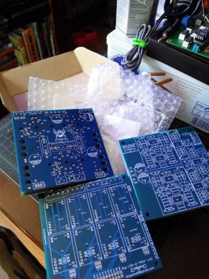
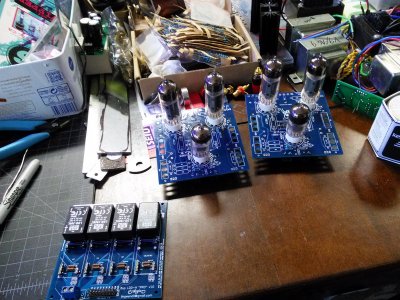
As soon as I finish one I'll use it to finish the bruiser build I've had sitting for the last year, I like the pendants but the girl likes the rapidLED enclosures better


As soon as I finish one I'll use it to finish the bruiser build I've had sitting for the last year, I like the pendants but the girl likes the rapidLED enclosures better
Here's the thread for the tube PCBs-
https://www.diyaudio.com/forums/tubes-valves/327541-6n2p-6cw5-design-toroidal-outputs.html
It's meant to be pretty universal for EL84 types, and once this set is tested I'll make versions for larger output tubes
https://www.diyaudio.com/forums/tubes-valves/327541-6n2p-6cw5-design-toroidal-outputs.html
It's meant to be pretty universal for EL84 types, and once this set is tested I'll make versions for larger output tubes
I drilled and tapped a pair of these-
https://www.digikey.com/product-det...poration/HSLCS-CALBL-012/1061-1042-ND/2632023
And run them with the matching PWM controlled coolers.
They're pretty neat, but a little small-


https://www.digikey.com/product-det...poration/HSLCS-CALBL-012/1061-1042-ND/2632023
And run them with the matching PWM controlled coolers.
They're pretty neat, but a little small-
Been busy working on other projects while waiting for parts to arrive via the "slow boat". They are starting to trickle in now and I have been populating some of the "L" boards as they come in.
Found two more issues with this initial batch of 8UP LDD "L" boards.
On the 8UP "EZ" there is a short from the U7 Vin+ pin to the ground plane on the back side.

On the 8UP "PRO" there is a short from the U3 PWM pin to the ground plane on the back side.

For those who have these boards, you can fix these issues by cutting the connections to the ground plane on the "back side" of the board with an X-Acto or utility knife at the above indicated locations.
I also found a solution to the undersized hole issue on the 8UP "L" boards using "5.08mm" screw terminal blocks. This also only applies to this initial batch of boards, as it has been fixed in the current design.
I am using 2 pin blocks - I am using 8 of these on the board instead of two 8 pin blocks. It should work with 8 pin blocks too, but you will have to disassemble the block first in order to compress the pins. Disassembly is not necessary with 2 pin blocks.
What I did was compress the long side off the pin using a pair of long handled (6" handles) needle nose pliers. You really need the leverage these give you. I measured the pins with a micrometer to be .026in x .041in (0.66mm x 1.04mm) before compressing. It is just a matter of compressing the longer side of each pin enough to get them to fit. It will still be a tight fit, but it sure beats soldering wires to the board.
Do not try drilling these holes out. There is copper plated onto the inside of these holes. Drilling them out will break the connection between the top of the board to the pad on the back side of the board.
Found two more issues with this initial batch of 8UP LDD "L" boards.
On the 8UP "EZ" there is a short from the U7 Vin+ pin to the ground plane on the back side.
On the 8UP "PRO" there is a short from the U3 PWM pin to the ground plane on the back side.
For those who have these boards, you can fix these issues by cutting the connections to the ground plane on the "back side" of the board with an X-Acto or utility knife at the above indicated locations.
I also found a solution to the undersized hole issue on the 8UP "L" boards using "5.08mm" screw terminal blocks. This also only applies to this initial batch of boards, as it has been fixed in the current design.
I am using 2 pin blocks - I am using 8 of these on the board instead of two 8 pin blocks. It should work with 8 pin blocks too, but you will have to disassemble the block first in order to compress the pins. Disassembly is not necessary with 2 pin blocks.
What I did was compress the long side off the pin using a pair of long handled (6" handles) needle nose pliers. You really need the leverage these give you. I measured the pins with a micrometer to be .026in x .041in (0.66mm x 1.04mm) before compressing. It is just a matter of compressing the longer side of each pin enough to get them to fit. It will still be a tight fit, but it sure beats soldering wires to the board.
Do not try drilling these holes out. There is copper plated onto the inside of these holes. Drilling them out will break the connection between the top of the board to the pad on the back side of the board.
Thanks for the info! I'll dig into the files tonight an make some more corrections.
Good tip on the pin compression, I'll have to try that. I was planning on running them hardwired but the terminals make life so much easier.
I mentioned on my diyAudio post that I found possible bugs on easyEDA that may be causing this, as it's been a persistent reoccurring issue throughout several designs, and a few others have mentioned similar issues as well. Sometimes nets will merge or rename to unique designations- the end result being pins that end up floating or tied to other nets, and we end up with weird issues
That's not the kind bugs we need when doing prototypes. Makes sense to use someone else's viewer to check your work. When I get a little time I was going to dive into easyEDA for some simple stuff I need. May be worth the while to look elsewhere. I forget what product it was, but about 10 years ago I used a product like that to reverse engineer some boards I was interested in at the time. I would expect today's products are much better.
I mainly use EasyEDA because it's online based and I don't have consistent access or time to use a PC based solution, most of my work is during downtime at work on Chrome OS devices. When I get a decent PC setup at home again I want to get into a more advanced PCB design program that is either cheap or free hopefully.
Files have been fixed, and reuploaded here-
https://github.com/Lingwendil/LDD-L-driver-PCBs-for-Aquarium-LED-lighting
Going to go back over them again with a fine-tooth comb a bit more, but so far that looks like the only other problems...
Just ordered a set of terminal blocks too, so I'll hopefully have a finished 8up H board this sunday, and if all goes well I can finally power up the big bruiser build that's been on back burner forever-
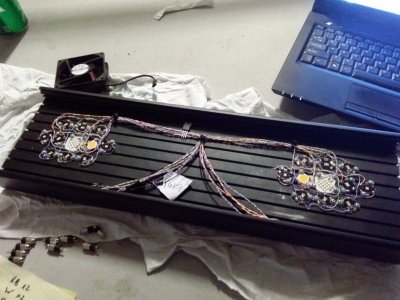
Current loadout per cluster (all luxeon other than the white and violet)-
Royal blue- 1x K16
White- 1x Citizen CLU028 97CRI 4000k
Cool blue- 4x
Cyan- 2x
Violet- 2x
Lime- 1x
Should be the perfect light for playing with on a 40 breeder with corals that like low, as well as moderate to somewhat higher light.
Thinking of swapping the Citizen white for a pair of Sunplus cool white, and maybe swapping the lime for mint. We'll see when i fire it up
https://github.com/Lingwendil/LDD-L-driver-PCBs-for-Aquarium-LED-lighting
Going to go back over them again with a fine-tooth comb a bit more, but so far that looks like the only other problems...
Just ordered a set of terminal blocks too, so I'll hopefully have a finished 8up H board this sunday, and if all goes well I can finally power up the big bruiser build that's been on back burner forever-

Current loadout per cluster (all luxeon other than the white and violet)-
Royal blue- 1x K16
White- 1x Citizen CLU028 97CRI 4000k
Cool blue- 4x
Cyan- 2x
Violet- 2x
Lime- 1x
Should be the perfect light for playing with on a 40 breeder with corals that like low, as well as moderate to somewhat higher light.
Thinking of swapping the Citizen white for a pair of Sunplus cool white, and maybe swapping the lime for mint. We'll see when i fire it up
Last edited:
@Lingwendil
I took a shot at creating a schematic in EasyEDA. Got the result I wanted. Not sure if a PCB could be created from this, but I may give it a try down the road as a learning exercise.
They have a few bugs in there. For the most part it works, but you have to really watch for side effects of various operations. And the "Undo" function has some real problems. Sometimes it works and and sometimes I found it undoing operations preceding the one I wanted to undo. And then it wouldn't "Redo". Finally just gave up on using it.
Tell me what you think.
I took a shot at creating a schematic in EasyEDA. Got the result I wanted. Not sure if a PCB could be created from this, but I may give it a try down the road as a learning exercise.
They have a few bugs in there. For the most part it works, but you have to really watch for side effects of various operations. And the "Undo" function has some real problems.
Tell me what you think.
Attachments
Looks good! I'll take a better look at it tomorrow morning.
On a nice note, I got a PCB stuffed and the fixture up over the tank-
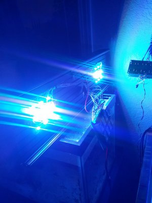
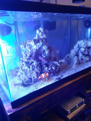
No issues so far, it's super nice to have it all on a single configurable board! This is seven drivers and one DC converter.
I'll give it a few days and I'll try to figure out an enclosure for it if all goes well. The wires on this fixture are super short so I'd like to put new cables on so I can put the drivers in a box under the aquarium stand.
On a nice note, I got a PCB stuffed and the fixture up over the tank-


No issues so far, it's super nice to have it all on a single configurable board! This is seven drivers and one DC converter.
I'll give it a few days and I'll try to figure out an enclosure for it if all goes well. The wires on this fixture are super short so I'd like to put new cables on so I can put the drivers in a box under the aquarium stand.
A followup to my post (#172 above) on cutting the grounds from pins on boards so affected.
It is best to solder in the socket pins or the LDD-L module itself first. This will protect the hole from inadvertent damage. I tried using an X-Acto knife but this proved to be difficult to get though the copper layer without cutting away more than I wanted. So I got out my Dremel (or use other rotary tool) and used the below cutter:

I does not matter if you cut into the base material below the copper layer (there are no internal copper layers).
The 8up "EZ" board needs to be cut completely around the pin.

The 8up "PRO" version needs to be cut all the way around except for the side with the trace leading to it. Be careful not to cut this trace, but if you do, you will have to solder in a jumper wire to bypass the cut.

Use a meter to check that there is no longer a connection between the pin and the ground plane.
It is best to solder in the socket pins or the LDD-L module itself first. This will protect the hole from inadvertent damage. I tried using an X-Acto knife but this proved to be difficult to get though the copper layer without cutting away more than I wanted. So I got out my Dremel (or use other rotary tool) and used the below cutter:
I does not matter if you cut into the base material below the copper layer (there are no internal copper layers).
The 8up "EZ" board needs to be cut completely around the pin.
The 8up "PRO" version needs to be cut all the way around except for the side with the trace leading to it. Be careful not to cut this trace, but if you do, you will have to solder in a jumper wire to bypass the cut.
Use a meter to check that there is no longer a connection between the pin and the ground plane.
Similar threads
- Replies
- 44
- Views
- 1,010
- Replies
- 8
- Views
- 381


