Tariq’s Reef-Pi Journey

t951

Community Member
View Badges
Joined
Feb 5, 2016
Messages
60
Reaction score
46
Location
Orlando, FL
Rating - 0%
0   0   0
Hello all,
So after having so-so reliability with my Apex, I have decided to build a reef-pi system. This new system will go on my smaller 24G tank for a long-term reliability test. My goal is to basically mirror the apex capabilities; temp, ph, lights, ATO, power heads and eventually dosing. To start with I have purchased the following.
  • Raspberry Pi Zero- W (already had this, but then got a different pi)
  • Raspberry Pi 4B (This has already given me a challenge that I am hoping you guys can guide me with).
  • PWM Converter for Mars Aqua
  • Isolated pH Probe Interface for reef-pi
  • Connector: 12" JST Connector on both ends
  • ML reef-pi hat
  • ADJ SRP8
  • MEAN WELL RS-50-5 AC to DC Power Supply Single Output, 5V 10 Amp 50W
  • StarTech.com 10' RS232 Serial Null Modem Cable - Null Modem Cable - DB-9 (F) to DB-9 (F)
  • Junction Box with Mounting Plate IP67 250x150x100mm (9.8"x5.9"x3.9")
  • MT3608 Step-Up Adjustable DC-DC Switching Boost Converter Power Supply Module 2-24V to 5V-28V 2A
  • Hilitchi 40-Pieces 2 3 4 5 Pin 16mm Thread Male Female Panel Metal Aviation Wire Wire Connector Plug Assortment Kit (2 Pin / 3 Pin / 4 Pin / 5Pin)
  • C2G 02882 DB9 Male Serial RS232 Add-A-Port Adapter Cable (11 Inches)
  • Mini Micro Sh 1.0 Jst 4-Pin Connector Plug Male with 100mm Cable & Female
  • Silicone rubber electrical wires 22AWG tinned copper single core electric wires
  • CQRobot Contact Water/Liquid Level Sensor for Raspberry Pi/Arduino.
  • Kastar AC Adapter, Power Supply LCD 12V 4A 48W for Low Voltage Devices
  • Mini Micro Sh 1.0 Jst 3-Pin Connector Plug Male With 100Mm Cable & Female
  • Temperature Sensor with Waterproof Cable with Stainless Steel Probe
  • 2.54mm 2/3/4/5 Pin Head Connector set Adapter Compatible with JST-XHP
  • Breadboard Jumper Wires 10cm 15cm 20cm 30cm 40cm 50cm 100cm
  • DB9 RS232 D SUB Male Adapter to 9 Position Terminal Breakout Board 2Pcs
  • Milwaukee Instruments MA911B/2 Double Junction Ph Electrode with 2 m Cable

Some of these are probably not needed, but I wanted to have everything and return whatever I don’t need.

Case:
Ok, now the first challenge is the case. I got the recommended one from the different threads, but it seemed too small. I ended up getting a larger project box. The new case has space and a nice board that it sits on. I read on one of the threads (I honestly cannot differentiate them all) that I may need to have a divider.
  • Question 1: Do I put a plastic wall vertically in the chamber, or just keep them apart? The answer will help me decide layout.

Layout:
  • Question 2: What is the best way to layout the components for future growth and keep everything tidy?
Raspberry Pi
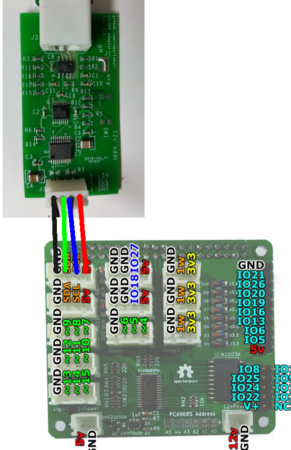
So, I was able to get reef-pi running on the smaller Wireless Zero W, but the pi-hat is too wide and would require a type of support brace.

  • Question 3: Does anyone have a brace design that I can print out? (I have a 3D printer).
In the pictures the Pi 3 is typically used, and being a tech nerd, I went and got a 4B. This pi requires a fan, and this is my biggest challenge. The case that contains the fan will not allow me to install the pi hat. I found this bracket at thingiverse:
This looks like a very unobtrusive design and there are a few others that look promising. So, here comes my first stupid question set;
  • Stupid question 1: can I use a ribbon cable to connect the ML pi-hat and not worry about a fan mount?
  • Stupid question 2: My gpio pin bar sits loosely, Do I need to solder it on? I have not seen it soldered.
  • Stupid question 3: What is the best way to solder? I am not used to soldering such tiny wires!

Power Supply:
The power supply I got has 1 V-in and 1 V-out:

power supply.jpg


I soldered the wires from the power supply to a both sides appropriately. (i.e. V+ connects to 5v and12v, and the same for the V- side) Is this ok, or should I get a different power supply?

power wiring.png


This is where I am today. The parts are here, I have soldered the wires to the boost converter and connected it to the hat. I am going to forge ahead here and reload reef-pi on the 4b and connect the DB9 to the ADJ.
  • Stupid Question 4: Since the pi 4b requires a fan, it does not make sense to have a fan inside a sealed enclosure, correct? I realize that water intrusion is a clear hazard, so should I sacrifice that for cooling? I can place the box in a lower risk area, but it will still be near the aquarium….
 
OP
OP
t951

t951

Community Member
View Badges
Joined
Feb 5, 2016
Messages
60
Reaction score
46
Location
Orlando, FL
Rating - 0%
0   0   0
Sorry, one last question. The fan is powered off of pins 1 or 2 and 14. However these pins are being used by the pi hat. Is it safe to stack the fan power and pi on the same pins?
 

Ranjib

7500 Club Member
View Badges
Joined
Apr 16, 2016
Messages
9,843
Reaction score
17,058
Location
Pleasant Hill, Concord
Rating - 0%
0   0   0
Keeping a plastic board to mount them is a good idea. There are bunch of 3d printable enclosures available under reef-pi group/tag. My recommendation will be to build enclosure and then brackets to mount then enclosure. Its safer to start small and get something working before embarking on more complex build. Make two builds if possible that way you have always one up and running for the failsafe purpose in case the other that you are tinkering with or testing with is out of service for some reason.
Its hard to how complex your build will be without fixing all the features you may end up using. I'll say start with ph, ato, temp , power in the same controller and then go from there.
 
OP
OP
t951

t951

Community Member
View Badges
Joined
Feb 5, 2016
Messages
60
Reaction score
46
Location
Orlando, FL
Rating - 0%
0   0   0
Ranjib,
Thanks for the reply. I think this is going to be fun, but a challenge. I have a dumb question in addition to the previous ones.
The raspberry pi has its own power plug, the pi hat has a 12v and a 5v.
I have a 5v power supply, and a power supply for 12v and the one that came with the raspberry pi.
I have ensured that the 5v is set to 5.1v

I have looked for pictures, but I cannot find which ones I should use. And finally, if I use the separate 5v supply and the 12v power supply, then I can omit the Switching Boost Converter. Is there a best practices consensus?

Thank you so much. I am going with reef pi because I see how amazing the group, and you, are.

t
 

Ranjib

7500 Club Member
View Badges
Joined
Apr 16, 2016
Messages
9,843
Reaction score
17,058
Location
Pleasant Hill, Concord
Rating - 0%
0   0   0
The 12v pins are required for adj power strip while the pi used by 5v (anything 5-5.2 v should be fine). You must supply the 5v for pi , while the 12v is only required if you want to control the adj powesttip
 

Bigtrout

Valuable Member
View Badges
Joined
Dec 16, 2018
Messages
1,189
Reaction score
2,826
Rating - 0%
0   0   0
Ranjib,
Thanks for the reply. I think this is going to be fun, but a challenge. I have a dumb question in addition to the previous ones.
The raspberry pi has its own power plug, the pi hat has a 12v and a 5v.
I have a 5v power supply, and a power supply for 12v and the one that came with the raspberry pi.
I have ensured that the 5v is set to 5.1v

I have looked for pictures, but I cannot find which ones I should use. And finally, if I use the separate 5v supply and the 12v power supply, then I can omit the Switching Boost Converter. Is there a best practices consensus?

Thank you so much. I am going with reef pi because I see how amazing the group, and you, are.

t
Ill chime in here a bit.
The 5v power input on the ML hat will power the pi and the hat itself. The 12 v power input will power whatever relays you want to use thru the uln2804 on the hat. Since you have a ADJ strip then this would need 12v. Since you already have a good 5v power supply, you can either use a convertor board or a seperate power supply for your 12v.

As for the hat...its just an convenience that it mounts on top of the pi but you can use a good quality ribbon cable as well.
 
OP
OP
t951

t951

Community Member
View Badges
Joined
Feb 5, 2016
Messages
60
Reaction score
46
Location
Orlando, FL
Rating - 0%
0   0   0
Perfect! Thanks for the response Bigtrout (I don't think I have ever thanked a fish before) and Ranjib!
I love pictures for reference, so I am going to try and take pics from diff angles to help the next person that wants to build a reef pi.

Thank you both again.
 
OP
OP
t951

t951

Community Member
View Badges
Joined
Feb 5, 2016
Messages
60
Reaction score
46
Location
Orlando, FL
Rating - 0%
0   0   0
Ok, so I have another series of questions.
1. Is it better to have a 12v step down to 5v or 5v up to 12v?
I have both step up and step down. My current box has the 5v mounted to the floor of the box and then on the top layer I have the Reef-Pi and ML Pi-Hat. I recall being told that the ph meter was sensitive and needed shielding. The plan is to have that mounted on the far side of the box on the top layer.
20191201_131239.jpg

20191201_131246.jpg


2. I have a chinese black box upgraded to SB reef lights. Are there detailed pictures that show the connections? This is what my box looks like:
20191201_132024.jpg


The connectors

20191201_132037.jpg


Zoom

20191201_132043.jpg


The pictures I have found weren't specific enough. The picture I have found shows a hole drilled out, and I would like to know how the cable from pihat connects to the light.
This is the picture I am referring to with the whole highlighted:
Inkedmars_LI.jpg
 

Michael Lane

Well-Known Member
View Badges
Joined
Aug 11, 2018
Messages
677
Reaction score
1,123
Rating - 0%
0   0   0
That's a snazzy mounting grid in your enclosure!

I would choose to use a 5v power supply and a step up converter to 12v. I think most components will require 5v, so the 5v supply seems to be a better choice. You'll usually get more stable power from the dedicated supply. Motors and relays can work with a bit more noise than the digital electronics, so the boost regulator can be appropriate. You'll also have a more consistent 5v demand than 12v.

The hole you have highlighted is left over from a previous modification I had done to mount an RJ11 connector. I have routed the reef-pi signal in through mini-xlr connectors. I mounted those by drilling out the original mounting hole for the dimmer knobs.

Here's how I would wire these together. The connection between the hat and the adapter can use one of the PWM ports. Mini-xlr is my favorite connector currently, but you can use whatever works well for you. The 4-pin JST connector in your light fixture plug into the adapter as shown below.
1575229778263.png
 
OP
OP
t951

t951

Community Member
View Badges
Joined
Feb 5, 2016
Messages
60
Reaction score
46
Location
Orlando, FL
Rating - 0%
0   0   0
Ok, so months have passed and I am now trying to get back into this project. So, I have most of it physically hooked up, but I have some possibly basic questions. I tried searching but got too many results.
My CQRobot water sensor should plugs into the ATO port on the ML pi-hat, but my sensor only has three wires and the ATO plug on the board has 4. How do I wire this?
Which port on the pi-hat do I plug my ph into? I2C?

Thanks again! Sorry for the long delay.
 

Michael Lane

Well-Known Member
View Badges
Joined
Aug 11, 2018
Messages
677
Reaction score
1,123
Rating - 0%
0   0   0
The pH board should hook up to either I2C port. The image below shows how to connect it. You have a V3 board, so the connectors are smaller, but the pinout is the same (GND, SDA, SCL, 5V). In fact, all the connectors have the same pinout as shown in this image.

Chwd1lq.jpg


I'm guessing this is the CQRobot optical liquid level sensor board? Based on the pinout and description, I believe it should be connected as shown below. You'll use the 3 pins on the right, leaving the 4th pin unconnected.

1591752293082.png
 

Bigtrout

Valuable Member
View Badges
Joined
Dec 16, 2018
Messages
1,189
Reaction score
2,826
Rating - 0%
0   0   0
You are amazing! Thank you for the fast response.
Hind sight 20/20......I should have listened to you and not gone with the micro-jst connectors....what a pain!
I buy premade jst tails and just splice things together to make the correct cable.
 
OP
OP
t951

t951

Community Member
View Badges
Joined
Feb 5, 2016
Messages
60
Reaction score
46
Location
Orlando, FL
Rating - 0%
0   0   0
That's exactly what I am doing, but as an older guy (turned 50 this week!) tiny things are getting to be a pain!
I have to say that you are more responsive than ANY other hardware vendor I have ever communicated with (20 years in IT is a lot of hardware vendors!)
Stay healthy and thanks again!
t.
 
OP
OP
t951

t951

Community Member
View Badges
Joined
Feb 5, 2016
Messages
60
Reaction score
46
Location
Orlando, FL
Rating - 0%
0   0   0
Michael,
Would it make sense to get your newer board? I want to order the Dosing Pump Adapter and if there are improvements or reasons to make the switch I could do that.....unless of course you have a new mega-awesome version in the works, in which case I will wait.

t
 

Michael Lane

Well-Known Member
View Badges
Joined
Aug 11, 2018
Messages
677
Reaction score
1,123
Rating - 0%
0   0   0
Michael,
Would it make sense to get your newer board? I want to order the Dosing Pump Adapter and if there are improvements or reasons to make the switch I could do that.....unless of course you have a new mega-awesome version in the works, in which case I will wait.

t
lol. I'm kicking around a new experimental version, but I don't know if it will work out, or if it will be way too much effort to assemble. Besides, it probably wouldn't really add any features for you. The biggest thing for me is that I'd like to use only a single 12v power source. I'd like to knock out a few more reef-pi features before I switch back to hardware. It'll probably be August before I get back to that.

The newer goby hat doesn't really offer anything new over the V3 board. It's an improved board layout for assembly, but retains the same core features.

If you decide you want to get a dosing adapter, I could help with some custom cables to make it easier to connect it.
 
OP
OP
t951

t951

Community Member
View Badges
Joined
Feb 5, 2016
Messages
60
Reaction score
46
Location
Orlando, FL
Rating - 0%
0   0   0
I appreciate your reply (not being a salesman, but an engineer). If you ever do make a new board, I will absolutely get one based purely off of your responsiveness and support. I would love a version that incorporated a modern testing solution (like reefbot, or the Neptune trident), and had a cool name, like Atlantis.
 
OP
OP
t951

t951

Community Member
View Badges
Joined
Feb 5, 2016
Messages
60
Reaction score
46
Location
Orlando, FL
Rating - 0%
0   0   0
OK, so I think I at some time may have cooked my pi-hat......
The pi-zero powers up nicely when plugged in using it's own power.
It does not power up when I connect power via the pi-hat 5v.
I measured the power coming out of the raspberry stock power (5.47v)
I used my variable power supply to try from 5.0 -> 5.47v Nothing
I also note that the power draw when doing this stays at .02 A
I checked the power at the pins on the pi-hat and I have the correct power there.

Is it possible the board is cooked?
Any tests I can run?
I disconnected the 12v power and related buck-board (also double checked the output of that as well when it was connected).
Would the pi-hat not power up if the sensors were wired, but had no connections (my temp, ATO, ph are connected to the hat, but there are no actual sensors hooked up.

I appreciate the guidance as always.

rpi_power.jpg vps1.jpg
 

When to mix up fish meal: When was the last time you tried a different brand of food for your reef?

  • I regularly change the food that I feed to the tank.

    Votes: 23 29.1%
  • I occasionally change the food that I feed to the tank.

    Votes: 30 38.0%
  • I rarely change the food that I feed to the tank.

    Votes: 20 25.3%
  • I never change the food that I feed to the tank.

    Votes: 5 6.3%
  • Other.

    Votes: 1 1.3%
Back
Top